102
Chapter 8 DETAIL PERFORMANCE SETTINGS
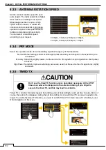
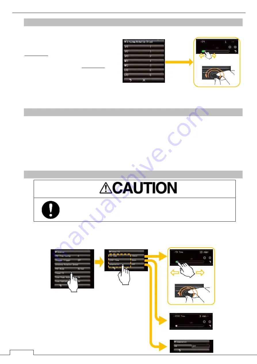
8.3.3 ANTENNA ROTATION SPEED
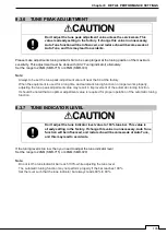
Set the scanner rotation speed for each
pulse length. The radar sensitivity is higher
when antenna is rotating in low speed.
Short range operation requires a high
speed antenna rotation to refresh the
screen as soon as possible. Long range
operation requires a low speed antenna
rotation to maintain a high sensitivity.
You can select a rotational speed
according to your request.
8.3.4 PRF MODE
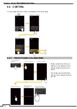
Select the operation mode of the transmitting repetition frequency of the transmitter.
Normal: Default setting is Normal. Both appropriate sensitivity and magnetron life expectancy are
considered.
Economy: Sensitivity slightly lowers, but the service life of magnetron is prolonged when short pulses
are used.
High Power: Sensitivity improves when long pulses are used, but the service life of magnetron is slightly
shortened.
8.3.5 TIMED TX
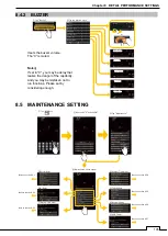
Timed TX is function that radar repeats transmitting and not transmitting by each set time minutes. But is of
course, the radar echo disappear during the not transmitting. As a result timed TX can save magnetron life
longer. To enable the timed TX function, you need to set ON Timed TX in main menu (5.12.7) after you set
ON of Adaptation in this menu.
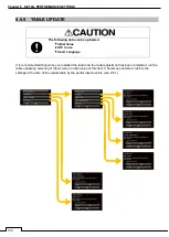
Don’t use the timed TX function unless absolutely necessary. At the STBY
time area, radar echo disappear in the antenna rotating. If you forget to
execute the timed TX, and this may lead to accidents.
or
or
0=48rpm, 1=42rpm, 2=36rpm, 3=30rpm,
4=27rpm, 5=24rpm, 6=20rpm, 7=16rpm
Summary of Contents for SMR-715 series
Page 1: ...MARINE RADAR EQUIPMENT INSTRUCTION MANUAL...
Page 2: ......
Page 15: ...xiii EQUIPMENT APPEARANCE NKE 1066 SCANNER UNIT NKE 2044 SCANNER UNIT...
Page 29: ...Chapter 1 INSTALLATION 3 1 2 3 DIMENSIONAL DRAWING OF DISPLAY MOUNTING...
Page 30: ...Chapter 1 INSTALLATION 4...
Page 32: ...Chapter 1 INSTALLATION 6 DESKTOP MOUNTING TEMPLATE Note Please note the paper size 182 257...
Page 34: ...Chapter 1 INSTALLATION 8 FLUSH MOUNTING TEMPLATE Note Please note the paper size 182 257...
Page 43: ...Chapter 1 INSTALLATION 17 NKE 2044 2FT SCANNER Fig 1 3 6 3 Fig 1 3 6 4...
Page 47: ...Chapter 1 INSTALLATION 21 Fig 1 4 1 3...
Page 51: ...Chapter 1 INSTALLATION 25 Fig 1 4 2 3...
Page 157: ...131 Chapter 10 AFTER SALE SERVICE 10 4 RADAR FAILURE CHECK LIST SMR...
Page 159: ...133 Chapter 12 SPECIFICATIONS Chapter 12 SPECIFICATIONS...
Page 160: ...134 Chapter 12 SPECIFICATIONS 12 1 SCANNER DIMENSION 12 1 1 NKE 1066 4 40 RUBBER PLATE...
Page 161: ...135 Chapter 12 SPECIFICATIONS 12 1 2 NKE 2044...
Page 162: ...136 Chapter 12 SPECIFICATIONS 12 2 DISPLAY DIMENSION 12 2 1 SMR 715 720...
Page 163: ...137 Chapter 12 SPECIFICATIONS...
Page 172: ...APPENDIX A 1 APPENDIX NKE 1066 1 5FT SCANNER INTERCONNECTION DIAGRAM FIG A1...
Page 173: ...APPENDIX A 2 NKE 2044 2FT SCANNER INTERCONNECTION DIAGRAM FIG A2...
Page 174: ...APPENDIX A 3 SMR 715 720 DISPLAY UNIT INTER CONNECTION DIAGRAM FIG A3...
Page 175: ...APPENDIX A 4 SMR 715 720 PRIMARY POWER SUPPLY DIAGRAM FIG A4...
Page 176: ...APPENDIX A 5 SMR 715 720 INTERCONNECTION DIAGRAM FIG A5...
Page 177: ...APPENDIX A 6 MEMO...
Page 187: ...APPENDIX A 16 DECLARATION OF CONFORMITY...
Page 188: ...APPENDIX A 17...
Page 189: ...APPENDIX...
Page 191: ...Chapter 3 ADJUST THE RADAR ECHO A 2...
Page 192: ...Chapter 3 ADJUST THE RADAR ECHO...


