43
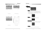
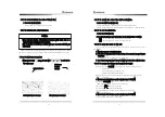
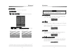
4.3.2 False Image
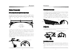
There is a possibility that non-existing targets may be shown or any existing
③a①ge③② may no③ be ②hown ③h①o④gh ③he image. Thi② image i② called vi①③④al image .
What mainly causes such false image as follows;
1. Shadow
Dipending on the installation position of antenna, the reflection may come back
af③e① colliding again②③ ③he f④nnel o① ma②③, which may c①ea③e ②hadow ca④②ing
the virtual image on PPI screen. In this case, the targets that are located at the
shodow direction may not be shown on the screen.
The existence
of ②④ch a ②hadow
may be figured out by checking if there is any
dim image or any unseen part, based on the reflection of sea level.
If ③he ②hadow occ④①②, ③he ④②e① need② ③o memo①ize ③he di①ec③ion in o①de① ③o
observe the targets with care.
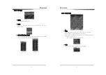
2. Side echo
There may be an image of arc wave line in the same distance from target image
on the screen. This is caused by the side lobe of which beam is radiated from
the antenna.
For this phase, it is easy to make a judgment when targets are fixed.
3. Secondary reflection
Fake images may be displayed as their directions are changed through being
reflected against the funnel or mast, which create shadow.
In this case, the images of targets are located at the mast direction that reflects
the radar wave.
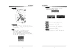
4. Multi-reflection image
Where there are any structures or big-sized vessels that are hidden behind
gigantic vertical line, multiple images by multi-reflection appear.
These images come out at intervals of every lamp line and among the lines, the
closest line to the own ship is the actual image of target.
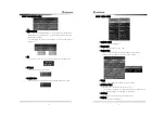
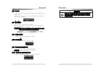
5. Radar interference
If there is any radar closely located that uses the same frequency, the
interference image by the radar appears on PPI screen. This interference turns
into various spots and appear in forms of many images but as the interference
does not appear in the same place, it may be distinguished from target image.
For the radar interference(
button), select
ON
in the function to diminish or
get rid of it
44
Chapter 5. Installation
!
5.1 Overview
•
Proper installation of Radar ensures the performance and safety of it during
operation and facilitates the maintenance and repair of it, you should carefully pay
attention to the proper of installation accoding to the instruction.
•
Antenna should be installed as high as possible after considering its weight.
•
Indicator should be installed inside Wheel House in order make observation
efficiently.
•
15m standard cable should be used between Antenna and Indicator.
5.2 Installation of Antenna
5.2.1 Selection of the installation place
!
*The specialist from Head Office or Local distributor should carry out installation work.
*Installation works carried out by unauthorized person can cause out of order.
performance failure Electric shock.
CAUTION
※
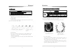
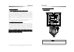
The place where there is no big obstructions on the level of ship s fore and afterside.
※
If there is a obstacle on the same level of antenna, it may cause a virtual image.
※
Especially when the virtural image appears on ship s fore and after side, it will be
difficult to observe and forecast the danger.
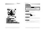
※
Avoid installing near funnel as it may cause the decrease in performance, the defect
due to heat, therefore it should be installed as far away from the funnel as possible.
※
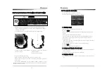
Please keep in mind that direction finding antenna and VHF antenna should be far
away from Radar Antenna.
(Please avoid the situation from tying up other cables with radar one)
Caution

