SRG-1150DN / SRG-1250DN / SN-100
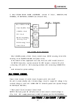
(if NBDP TERMINAL is set.)
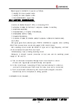
⑵ PROTECTION and ALARM
In overload voltage +32v, make power off and built circuit to prevent conversing
voltage not to demage equipment even in conversing voltage.
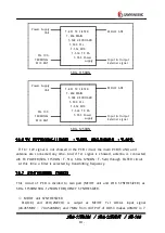
10.3 TRANSMITTING CIRCUIT
Bias voltage operate and maintain fitting voltage to press PTT(transmitting switch)
installed in HAND MIC and virus voltage even in output amp for excitation is
supplied and receive sound- input from MIC installed and after amplify audio- input in
AF
AMP(T- 452 Q34, Q36), in BALANCE MODULATION, mixed with BFO and in S S B
FILTER(XL2) filter low frequency part.
So, this signal is mixed in 49MHZ LOCAL and IC3 and amplify in 49MHZ+IF=2'nd
IF AMP(Q29).
This signal pass 49.455MHZ FILTER and is mixed in F
C
+49.455MHZ LOCAL and
IC4 is amplify in RF AMP(Q31,Q32) and pass LOW PASS FILTER.
This signal go to external RF AMPLIFIER and pass TX FILTER(T- 551) and go to
POWER SPLITER(T- 516_1) and pass T1,T2 and is separated as PWR AMP A(T- 514)
and PWR AMP B(T- 514).
This signal go to TX PWR CONBINER(T- 516_2) and is combined and after go to
DSC TX FILTER(T- 517) and amplify, in the selected TX LOW PASS FILTER, remove
spurious and pass antenna terminal and go to ATU and match transmitting
frequency and antenna frequency and transmit through antenna.
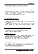
10.4 MF/HF RECEIVING CIRCUIT
Receiving signal in whip antenna pass band filter and after filter, amplify in
ultrashort amplifier T- 454(Q13, Q14) and in 1‘ st MIXER, fC+49.455MHZ LOCAL and
BALANCE MIXER and make IF 49.455MHZ.
This signal pass 455MHZ FILTER to become filtering and in amplifier Q9, amplify
and be balance mixed in 2‘ nd LOCAL 49MHZ and 2’ nd MIXER Q7, Q8 and make
455KHZ IF.
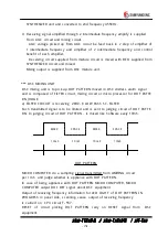
This signal become filtering through J 3E(XL2), H3E(XL1) FILTER according to
MODE.
Again, amplify in Q1,IC6 and mix SSB and H3E in IC7.

