15
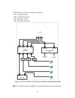
multi-switch (4 inputs and 4 outputs) configuration.
RF1: Low Band Vertical
RF2: Low Band Horizontal
RF3: High Band Vertical
RF4: High Band Horizontal
RF1 RF2
RF3
RF4/
ACU
IRD #4
IRD #3
IRD #2
110~220VAC
50~60Hz
PC
Diagnostics
ANTENNA
Antenna Control Unit
(ACU)
RECEIVER
Vertical
/Low
Horizontal
/Low
Horizontal
/High
Vertical
/High
OUT1
OUT2
OUT3
OUT4
4X4
Multiswitch
RF
RF
RF
RF
Master IRD
SAT IN
TV
Figure 2-15 Four Satellites TV Receivers Installation
with European LNB
NOTE: If you want use more satellite TV receivers than four, you can choose 8
Summary of Contents for SUPERTRACK SDA-390
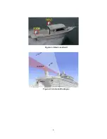
Page 7: ...3 Figure 2 2 Best Location II Figure 2 3 Antenna Blockages...
Page 11: ...7 Figure 2 7 Tighten the nuts from below...
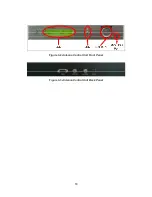
Page 22: ...18 Figure 3 2 Antenna Control Unit Front Panel Figure 3 3 Antenna Control Unit Back Panel...
Page 36: ...32 Connection Staus Display of LCD Figure 4 2 Connection Status SDA 390 with PC...
Page 39: ...35 Figure 4 5 Satellite List Update Step 2...
Page 48: ...44 C N Graph You can see the graph of C N on Antenna State Figure 4 13 C N Graph...
Page 55: ...51...

