San Telequip (P) Ltd.,
504,505 Deron Heights, Baner Road
Pune 411 045, India
Phone : +91-20-27293455, 9764027070, 8390069393 Connecting. Converting. Leading!
email :
3.8 Apply to all serial: Select “On” to make same setting for both 2 Serial ports. Select “Off” will pop up the
section of 2
nd
Serial port.
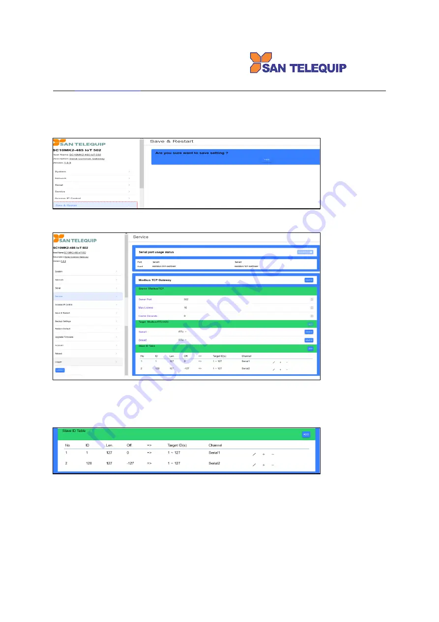
3.9 Up to now, setting is successfully configured and saved temporarily. Please go to “Save & Restart” to click
“YES” will save configuration and reboot this device to work. You may hold this action until configurations of
all sections are completed.
3.9 Service: Modbus TCP Gateway - Select both Serial1 and Serial2 at the same time against a specified TCP
socket port commonly.
3.9.1
Server Port: to input TCP port number.
3.9.2
Max Listens: to input number of remote connection. Be careful of too many connection decrease
performance.
3.9.3
Modbus RTU/ASCII: to RTU or ASCII selectable.
3.9.4
Slave ID Table: “pen symbol“ to edit content, +” to add line, “-“ to reduce line.
.
3.9.5
Item “Target ID(s)”: this is real ID of RTU devices.
3.9.6
Item “ID”: this is the mapping ID for “Target ID(s)”. It comes from “offset” function to change the ID
number of “Target ID(s)”. For example the ID number 5, 7 are mapping from Target ID(s) 3, 4. Remote
Master query ID 5,7 but actually it query ID 3,4.
3.9.7
“Len.”: Length of ID means several RTU devices line up in a serial port.
3.9.8
“Off.”: Offset value to add or to minus numbers of “Target ID(s)” make new ID numbers for Remote
Master to query.
3.9.9
Notice that mapping “ID” should not be duplicate in the “Len.”(Length) of other ID otherwise the query
will fail.


