34
S&C Instruction Sheet 716-504
Operation
Understanding Trip-Free Operation
The stored-energy mechanism has an
instantaneous trip-free capability. If the
Series 2000 Circuit-Switcher is closed into a
fault sensed by the user-furnished relaying,
the mechanism will immediately trip. To
accomplish trip-free operation, the stored-
energy mechanism uses two spring assemblies:
one for closing and one for opening. Both
springs are charged by the operator motor
before the circuit-switcher can be closed.
Recharging time after a trip operation
is approximately 5 seconds for Model 2020
Circuit-Switchers rated 69-kV through 138-kV.
Electrical Operation
To open
, press the TRIP pushbutton or send a
remote trip signal to the switch operator. See
Figure 30 on page 26.
The opening latch in the stored-energy
mechanism will release, discharging the open-
ing spring. This action opens the interrupters
and forces the opening and closing pistons in
the stored-energy mechanism downward. The
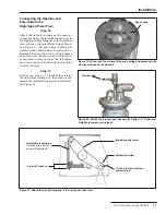
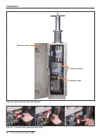
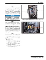
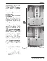
stored-energy indicator will travel to the DIS-
CHARGED window. See Figure 42 on page 35.
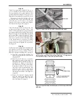
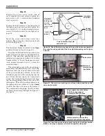
The switch-position indicator on the high-speed
base will move to the
Open
position. See Figure
41. If the position-indicating lamp option (Cata-
log Number Suffix “-M”) has been specified, the
green lamp will light. See Figure 30 on page 26.
After opening, the motor-driven cam in the
stored-energy mechanism will immediately start
rising, charging both the opening and closing
springs. When the opening spring latches, the
indicator will be visible in the CHARGED win-
dow. See Figure 42 on page 35. Simultaneously,
the take-off shaft at the rear of the operator
housing will turn to drive the interphase pipe
assembly, opening the disconnect.
The total opening time for the circuit is
6 cycles.
To close
, press the CLOSE pushbutton or
send a remote close signal to the switch opera-
tor. See Figure 30 on page 26.
The motor-driven cam in the stored-energy
mechanism will retract. Simultaneously, the
take-off shaft at the rear of the operator housing
will turn to drive the interphase pipe assembly,
closing the disconnect. When the disconnect has
closed, the closing latch will release, discharging
the closing spring and closing the interrupters.
The switch-position indicator on the high-speed
base will move to the
Closed
position. See Fig-
ure 41 on page 34. (The window will continue
to show the “CHARGED” indicator. See “Under-
standing Trip-Free Operation” on page 34.)
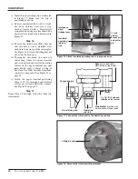
Figure 41. Switch-position indicator in the OPEN position. Switch-position
indicator in the CLOSED position.

