S&C Instruction Sheet 761-507
15
Installation
Installing Operating Handle
●
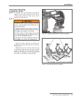
STEP 17.
Mount the operating handle assembly as shown
on the erection drawing. At the same time, use
one of the mounting bolts to attach one end of the
ground strap (the end with the grounding
connector attached) to the handle mounting
plate.
■
See Figure 20.
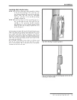
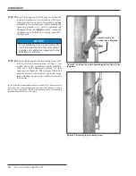
STEP 18.
Install the lowest vertical operating-pipe sec-
tion by threading one end of the pipe into the
coupling on the operating handle assembly.
Approximately
¼
inch (6 mm) of thread should
extend through the coupling. Tighten the lock-
nut. See Figure 21.
●
If the shipment includes an S&C Type AS-10 Switch Operator, as sig-
nified by the addition of the standard minor modification suffix “-S8” or
“-S9” to the erection drawing number, refer instead to S&C Instruction
Sheet 769-510, “S&C Switch Operators—Type AS-10,
Instructions for
Installation
." If the shipment includes an S&C 6801M Automatic Switch
Operator, as signified by the addition of standard minor modification
suffix “-S16” to the erection drawing number, refer instead to S&C
Instruction Sheet 1045M-510 .
■
The grounding recommendations described in this document may
differ from the standard operating and safety procedures of cer tain
electric utility companies . Where a discrepancy exists, the operating
procedures of the electric utility apply .
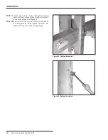
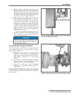
Figure 20. Mounting the operating handle.
Figure 21. Installing the lowest operating pipe section into the
operating handle assembly.


