S&C Instruction Sheet 761-507
9
Installation
Uncrating the Switch
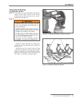
STEP 3.
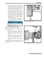
Remove the switch from its crate. See Figure 5.
Protect the bearings from contami nation by dirt,
mud, oil, etc. If necessary, use blocks to keep the
bearings clear of the ground.
For tiered-outboard mounting configura tion
switches proceed to Step 4 below.
For vertical mounting configuration switches
proceed to Step 9 on page 11.
Lifting Tiered-Outboard Mounting
Configuration Switch
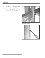
STEP 4.
To minimize time-consuming fi nal adjust ments,
make sure the switch is fully closed. Tie the
switch blades to their station ary main contact
assemblies. See Figure 6.
STEP 5.
WARNING
DO NOT lift the switch by rigging to the live
parts . Avoid allowing the switch to swing
while lifting .
Lifting the switch by the live parts will dam-
age the switch . Rough handling may cause
damage to the blades and contacts .
Failure to lift the switch properly can result
in switch damage, causing improper opera-
tion, arcing, or electrical shock .
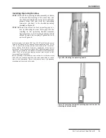
Hoist the switch using the two lifting eyes
attached to the top switch pole-unit base. See
Figure 7.
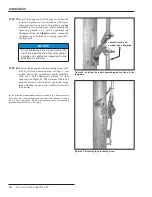
Unbolt the 4-inch (102-cm) x 4-inch (102-cm)
wood frame skid after the switch is hoisted to the
vertical position. This frame prevents damage to
the live parts of the bottom switch pole, as the
switch is being hoisted.
Figure 5. Uncrating the switch.
Figure 7. Hoisting the switch pole into position.
Figure 6. Tieing the switch blade to the main contacts.
4-inch (102-mm)
×
4-inch (102-mm)
wood frame skid


