S&C Instruction Sheet 761-545 17
Installation
Checking Alignment
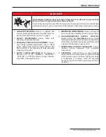
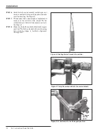
STEP 20.
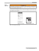
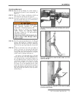
Remove the ties holding the switch blades to
their stationary main contact assemblies. See
Figure 22.
STEP 21.
Remove the 45-degree positioning stud from
each rod guide. See Figure 17 on page 15.
STEP 22.
Open and close the switch slowly to ensure no
operational difficulties are encountered due to
undetected damage in shipping.
WARNING
Open and close the switch slowly ONLY
when checking alignment or making
adjustments to the de-energized switch .
When opening or closing an energized
switch, swing the operating handle
vigorously through its full travel without
hesitation at any point .
Failure to operate the switch properly can
result in arcing, switch damage, serious
injury, or death.
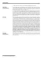
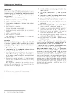
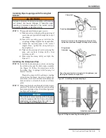
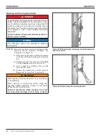
STEP 23.
Move the operating handle slowly to the
Closed
position. See Figure 23. A definite resistance
should be felt at the end of the stroke, indicating
all slack in the operating linkage has been taken
up.
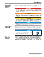
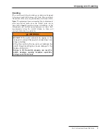
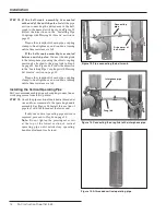
STEP 24.
If there is still slack, repeat the procedure in
Step 18 but move the operating handle more
than 20 degrees in the opening direction before
torquing the clamp bolt on the lowest rod guide
(or bell-crank) coupling. See Figure 24.
Conversely, if considerable force is needed
to move the handle to the fully
Closed
position,
or if the handle does not swing 180 degrees to
the fully
Open
position, loosen the clamp bolt
on the lowest rod guide (or bell-crank) coupling
and move the handle to a position less than
20 degrees from the
Closed
position. Then
torque the clamp bolt on the lowest rod guide (or
bell-crank) coupling. Proper “resistance” in the
operating linkage is essential to ensure positive
switch closure.
Figure 22. Removing the tie at the stationary main contact
assembly.
Figure 23. Verifying the stack has been taken up in the
operating linkage.
Tie
Figure 24. Torquing the clamp bolt at the lowest rod guide
(or bell-crank) cou pling.
Clamp bolt

