background image

2    S&C Instruction Sheet 761-545

Introduction

Qualified 

Persons

 WARNING

Only qualified persons who are knowledgeable in the installation, operation, and maintenance 
of overhead and underground electric distribution equipment, along with all associated hazards, 
may install, operate, and maintain the equipment covered by this publication . A qualified person 
is someone who is trained and competent in:
•  The skills and techniques necessary to distinguish exposed live parts from nonlive parts of 

electrical equipment

•  The skills and techniques necessary to determine the proper approach distances corresponding 

to the voltages to which the qualified person will be exposed

•  The proper use of special precautionary techniques, personal protective equipment, insulated 

and shielding materials, and insulated tools for working on or near exposed energized parts 
of electrical equipment

These instructions are intended ONLY for such qualified persons . They are not intended to be a 
substitute for adequate training and experience in safety procedures for this type of equipment .

Read this  

Instruction 

Sheet

NOTICE

Thoroughly and carefully read this instruction sheet and all materials included in the product’s 
S&C Instruction Handbook before installing or operating your Alduti-Rupter Switch . Familiarize 
yourself with the Safety Information and Safety Precautions on pages 5 through 7 . The latest 
version of this publication is available online in PDF format at 

sandc.com/en/support/

product-literature/ .

Retain this  

Instruction 

Sheet

This instruction sheet is a permanent part of your Alduti-Rupter Switch. Designate a location where 
you can easily retrieve and refer to this publication. 

Summary of Contents for Alduti-Rupter

Page 1: ...fety Precautions 7 Shipping and Handling Inspection 8 Packing 8 Handling 9 Installation Operating Pipe Preparation 10 Mounting to Wood 10 Uncrating the Switch 10 Attaching Couplings to Switch Poles 10...

Page 2: ...equipment insulated and shielding materials and insulated tools for working on or near exposed energized parts of electrical equipment These instructions are intended ONLY for such qualified persons...

Page 3: ...C Descriptive Bulletin 761 31 TORONTO ONTARIO M9W 1G4 MADE IN CANADA GTB 324R21 MADE IN CANADA GTB 2907R11 S C ELECTRIC CANADA LTD TORONTO ONTARIO M9W 1G4 S C ELECTRIC CANADA LTD Proper Application W...

Page 4: ...any special warranty provisions as set forth in the applicable product line specification bulletin are exclusive The remedies provided in the former for breach of these warranties shall constitute th...

Page 5: ...cautions are not followed NOTICE NOTICE identifies important procedures or requirements that can result in product or property damage if instructions are not followed Following Safety Instructions If...

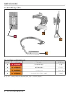
Page 6: ...Number A DANGER Electrocution Hazard G 6580 B WARNING Piercing Set Screws G 3176R1 C WARNING Handle Operation G 4400R5 D WARNING Electrocution Hazard Grounding Strap G 6596 This part is a tag to be r...

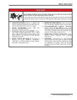
Page 7: ...othing in accordance with safe operating procedures and rules 4 SAFETY LABELS AND TAGS Do not remove or obscure any of the DANGER WARNING CAUTION or NOTICE labels and tags Remove tags ONLY if instruct...

Page 8: ...s insulating section in vertical operating shaft S2 One Cypoxy Insulator unit in vertical operating shaft S3 Insulated interphase sections and one fiberglass insulating section in vertical shaft S4 In...

Page 9: ...ly Closed position during installation of the interphase and vertical operating pipe sections S C recommends tying the switch blades to their jaw contacts with wire or a cable tie WARNING DO NOT lift...

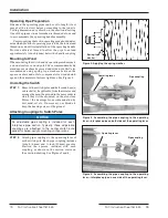
Page 10: ...e coupling Mounting to Wood When mounting the switch and its operating mechanism to a wood structure or wood pole S C recommends suitably sized square washers be placed under the nuts S C also recomme...

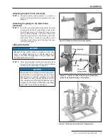
Page 11: ...les by rigging on the live parts or subject these parts to undue stress from slings or fall lines Misalignment of the contacts and the interrupters may result STEP 5 Hoist the individual switch poles...

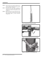
Page 12: ...re the switch is fully closed Tie the switch blades to their stationary main contacts See Figure 9 STEP 8 Makesurethebell crankisheldinthe45 degree position The bell crank and bell crank bearing have...

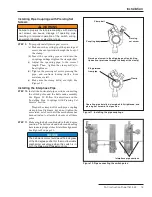
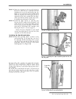
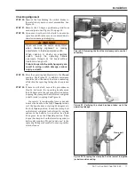
Page 13: ...cting the switch poles and the bell crank assembly See Figure 12 Follow the directions in the Installing Pipe Couplings with Piercing Set Screws section Torque the clamp bolt of each pipe coupling cla...

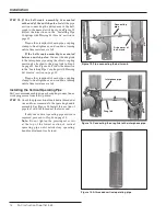
Page 14: ...Set Screws section on page 13 Torque the clamp bolt of each pipe coupling clamp to final tightness and continue turning until a firm resistance is felt Installing the Vertical Operating Pipe S C recom...

Page 15: ...Operating Handle STEP 16 Mount the operating handle as shown on the erection drawing At the same time use one of the operating handle mounting bolts to attach one end of the grounding strap the end wi...

Page 16: ...ng handle adjustment is attained STEP 19 Fasten the free end of the grounding strap to the lowest vertical operating pipe section a few inches above the operating handle assembly with the U bolt conne...

Page 17: ...e should be felt at the end of the stroke indicating all slack in the operating linkage has been taken up STEP 24 If there is still slack repeat the procedure in Step 18 but move the operating handle...

Page 18: ...ck bracketsotheinterlockbolt whenextended engages a slot in the locking disc on the operating handle See Figure 25 STEP 26 Block one of the two slots in the locking disc with the blocking screw provid...

Page 19: ...erly can result in arcing switch damage serious injury or death Make sure the following conditions exist a With the operating handle as far as it will go in the closing direction all main contacts of...

Page 20: ...ase the effective length of the interphase operating pipe Torque the clamp bolt of each pipe coupling clamp to final tightness Tighten the associated piercing set screws piercing the pipe and continue...

Page 21: ...and switch have been attained torque the bolts on the driving arm of the adjust able bell crank to final tightness NOTICE After readjusting retighten the locknut on each adjustable pipe coupling take...

Page 22: ...oves in the opening direction the blade shunt contact must firmly engage the interrupter hous ing before the blade disengages from the jaw contact The shunt contact may be bent as required to conform...

Page 23: ...ely apply a liberal coating of Penetrox A to the brushed surfaces b Wire brush each terminal pad of the interrupter switch and apply a coating of Penetrox A Then bolt the connectors to the terminal pa...

Page 24: ...OTICE This interrupter switch is not intended for breaking fault currents STEP 30 Remove the padlock from the locking bar on the operating handle assembly Withdraw the locking bar See Figure 34 a Ifth...

Reviews: