S&C Instruction Sheet 761-545 21
Installation
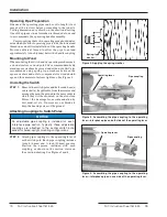
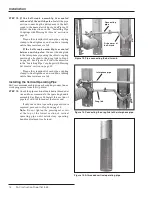
Loosen the two clamp bolts on the drive
a r m of the ad justable bell cra nk.
●
See
Figure 32. Shorten the drive arm of the adjust-
able bell crank one step [
1/8
-inch (3.2 mm)] and
retighten the bolts. Shortening the drive arm
increases switch blade travel. Then, readjust
for full operating-handle travel as described in
Steps 23 and 24 on page 17.
Repeat this procedure—shortening the
driving arm of the adjustable bell crank in
one-step increments and readjusting for full
operating handle travel—until full switch-blade
travel is attained.
When satisfactory travel adjustment of the
operating handle and switch have been attained,
torque the bolts on the driving arm of the adjust-
able bell crank to final tightness.
NOTICE
After readjusting, retighten the locknut on
each adjustable pipe-coupling take-up
screw, the clamp bolt and piercing set screw
on the pipe coupling at the rod guide (or
bell crank) immediately above the operating
handle, and the clamp bolts on the adjustable
lever arm of the bell crank .
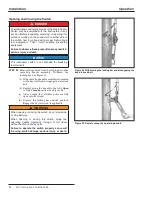
Figure 32. Shortening the drive arm of the adjustable bell
crank.
Clamp
bolts
Drive arm
●
For the tiered-outboard switch mounting configuration, no bell-crank
is used . In that case, switch-travel adjustment may be accomplished at
the adjustable (upper) rod guide . (Lengthening the driven arm increases
the amount of switch travel .) Then, readjust for full operating-handle and
switch-blade travel as described in Steps 23 and 24 on page 17 .

