10
S&C Instruction Sheet 1025-510
Installation
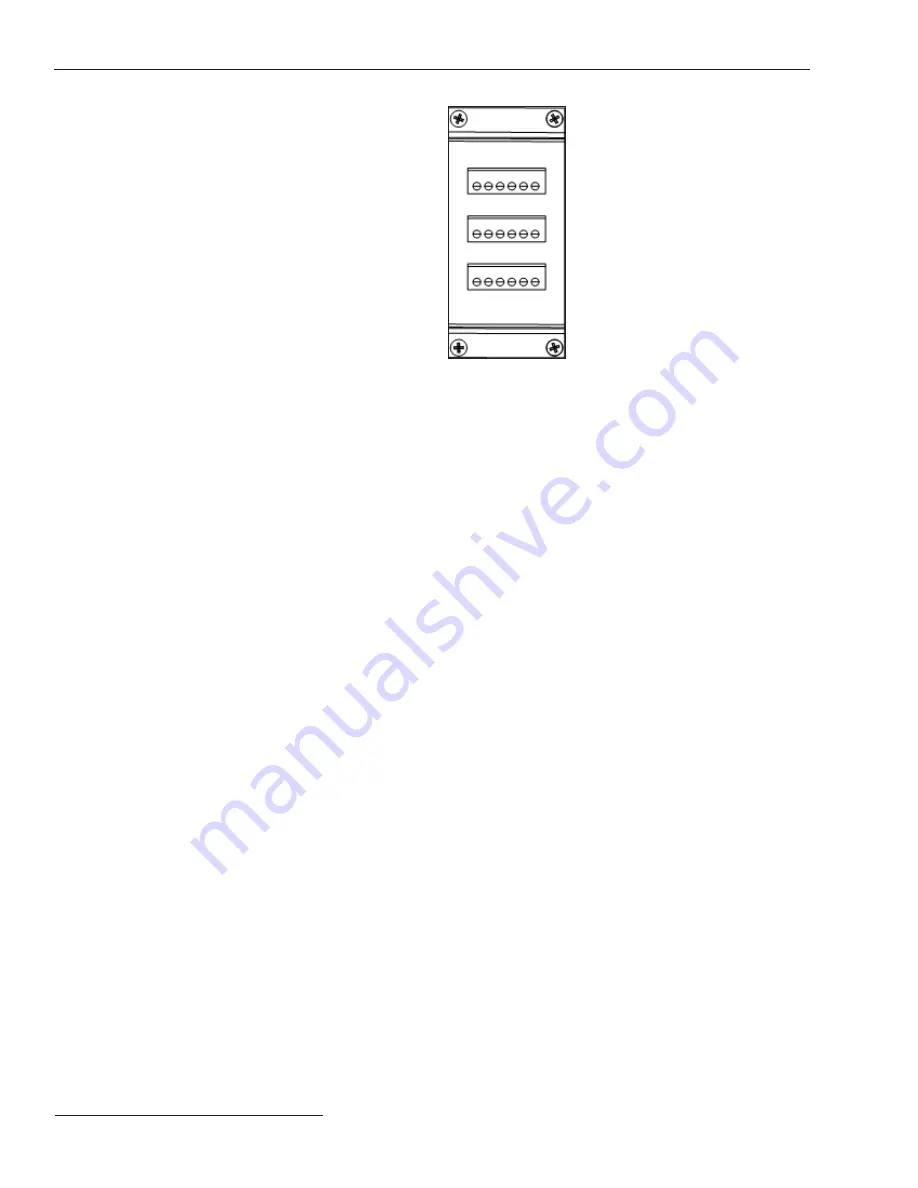
Figure 4. An RS-485 connector module.
RS-485 Connector Module
A three-terminal RS-485 connector module comes
standard with the GridMaster controller. See Figure 4. This
module provides three RS-485 screw terminals with six
ports. Pinouts are shown in the “Module Pinouts” section
starting on page 15.
To connect to a RS-485 connector module, connect
three 12– 30 AWG wires to the screw terminals associated
with the desired port and tighten the screws until they bot-
tom out. Do not leave the wires unsecured. The maximum
recommended length of wire is 1000 meters (3281 feet).
There is no required order for use of the screw terminals.
When using stranded wire, S&C recommends coating the
stranded ends with tin-solder before insertion into the
screw terminals.
Note:
The RS-485 connector module can communicate
at speeds up to 115200 baud and can be used to acquire
data from any compatible IED, including those using the
Modbus protocol. Third-party converters are available to
convert from RS-485 to RS-232 or RS-422.
All ports are configured as Data Terminal Equipment
(DTE). Both the send and receive registers of each port
have a 16-byte-first-in, first-out (FIFO) and ports have
16C550-compatable universal asynchronous receiver/
transmitters (UARTs). Individual modem handshake con-
trol signals are supported for all ports.


