STEP 6.
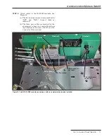
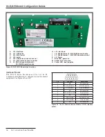
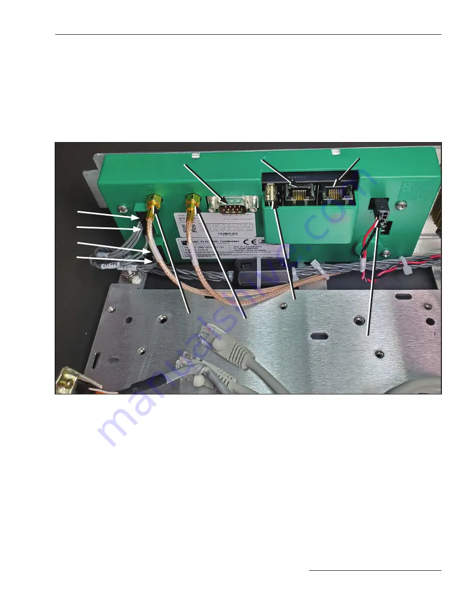
Attach cables to the Wi-Fi/GPS module. See
Figure 14.
(a) The two antenna connectors are marked for
“GPS” and “Wi-Fi.” Connect them as
indicated.
(b) The three gray cables are marked for the
appropriate connector. Connect them from
top to bottom in this order: J18, J17, and J16.
Connector J15 is not used.
Communication Module Retrofit
Figure 14. The R3 Wi-Fi/GPS module connections, with no communication device installed.
GPS antenna
Ethernet 1
Ethernet 2
USB connector
(not used)
Polarized power
connector
Serial
Wi-Fi antenna
J18
J17
J16
J15
S&C Instruction Sheet 766-526 11


