2 S&C Instruction Sheet 766-546
NOTICE
To disable automatic load restoration
through the IntelliTeam® SG Automatic
Restoration System (if furnished), select:
IT SG Operation – Disabled.
To disable Loop Restoration (if furnished),
select: Loop Restoration – Disabled.
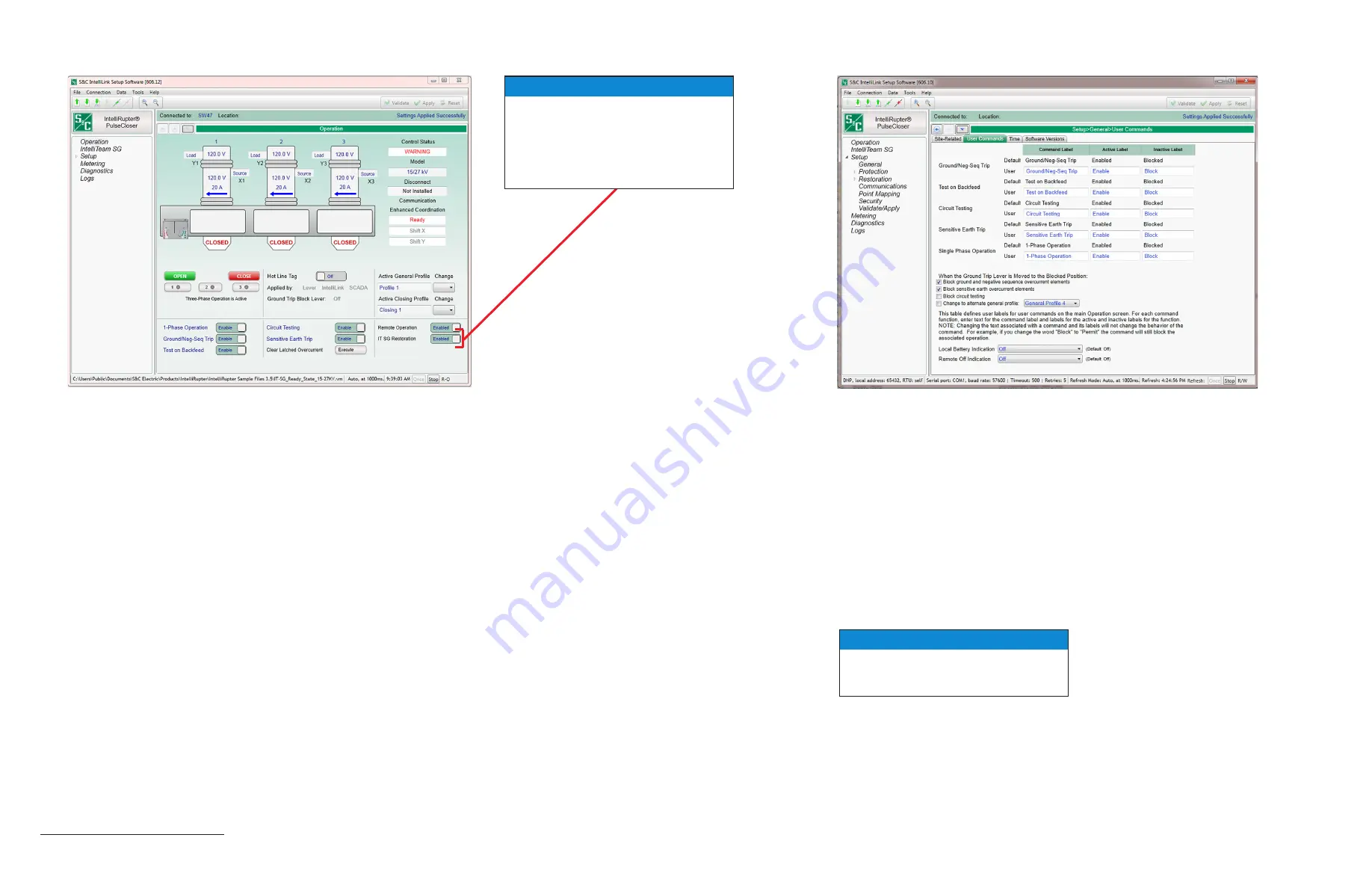
Match the location of the interrupter open/close/ready lever on the
IntelliRupter fault interrupter to the open/close/ready lever on this
screen.
•
Poles are labeled left to right, configured here as
A, B,
and
C.
•
X and Y terminal designations are configurable and affect direc-
tionality. The default configuration is:
Upper terminals pads (Y1, Y2, and Y3) are labeled
Y, and
Lower terminal pads (X1, X2, and X3) are labeled
X.
•
Voltage is shown for the three poles at each terminal pad. Phase-
to-ground voltage
(
1-grd, 2-grd,
and
3-grd), or phase-to-phase
voltage (
1-2, 2-3, and 3-1) can be selected.
•
Interrupter open/close indicators match the indicators on IntelliRupter
fault interrupter, in this cas
e they are
OPEN.
•
When IntelliRupter fault interrupter has tripped open, the state
of each pole is shown, for example:
TESTING-SEF, LOCKOUT-
VOLTS
(lockout on voltage trip), or
LOCKOUT-FREQ
(lockout on
frequency trip). For
LOCKOUT-OC
(lockout on overcurrent trip),
a lightning bolt indicates the faulted phase(s) on the side the fault
occurred. The current on each pole at the time of tripping is also
shown.
•
When IntelliRupter fault interrupter is closed, load current and cur-
rent direction are shown for each pole.
•
Control Status
shows the status of the protection and control
module (in this case
ALARM). It may also display: OKAY,
WARNING, ERROR, MAINT MODE, or SETTINGS MISMATCH.
•
Enter a Command Label, an Active Label, and an Inactive Label—for every User Command.
These will be displayed on the
Operation
screen.
Text entered for Active or Inactive Labels
does not change their functionality.
•
Ground Trip Blocked Functions—check to enable desired functionality.
•
Local Battery Indication—select
On
if a battery is installed, then the Status Indicator on the
Control Module will flash
½ second every second
when the battery is Low, Bad, or Disconnected.
If no battery is installed, select
Off
.
•
Remote Off Indication—the Status Indicator on the Control Module can be configured to display
solid on when
Remote Operation
is disabled.
•
Connected to:
and
Location:—at the top of the screen, show the name and address of the
IntelliRupter fault interrupter connected through IntelliLink or IntelliLink Remote software.
•
Disconnect
shows the position of the visual disconnect:
OPEN
,
CLOSED, or Not Installed.
•
Loop Restoration or Communication Enhanced Coordination
status is displayed when when either feature is furnished and
Enabled
.
•
OPEN
and
CLOSE buttons trip and close the interrupters. A single
phase can be operated if
Single Phase Operation
is
Active
.
•
Single Phase Operation
,
Ground Trip Block, and Test on
Backfeed
can be enabled or disabled.
•
Hot Line Tag
can be enabled or disabled, and the application
method is indicated.
•
Circuit Testing, and Sensitive Earth Trip can be enabled or
disabled.
•
Clear Latched Overcurrent can be executed.
•
Active General Profile and Active Closing Profile can be
selected.
•
Remote Operation
can be enabled or disabled.
•
IT SG Restoration
can be enabled or disabled.
•
Connected to:
and
Location:—at the top of the screen, show the
name and address of the IntelliRupter fault interrupter connected
through IntelliLink or IntelliLink Remote software.
IntelliLink
Setup Software: Setup—General—User Commands
Screen
IntelliLink
®
Setup Software: Operation
Screen
NOTICE
Refer to S&C Instruction Sheet 766-530
for detailed information about IntelliRupter
fault interrupter configuration.


