background image

S&C Instruction Sheet 766-510  

3

Understanding  

Safety-Alert 

Messages

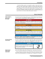
Several types of safety-alert messages may appear throughout this instruction sheet and 
on labels attached to the IntelliRupter fault interrupter. Familiarize yourself with these 
types of messages and the importance of these signal words:

  DANGER

“DANGER” identifies the most serious and immediate hazards that will likely 
result in serious personal injury or death if instructions, including recommended  
precautions, are not followed.

  WARNING

“WARNING” identifies hazards or unsafe practices that can


result in serious  

personal injury or death if instructions, including recommended precautions, are 
not followed.

  CAUTION

“CAUTION” identifies hazards or unsafe practices that can result in minor 


personal injury if instructions, including recommended precautions, are not followed.

NOTICE

NOTICE

” identifies important procedures or requirements that can result in 


product or property damage if instructions are not followed.

Following Safety 

Instructions

If you do not understand any portion of this instruction sheet and need assistance, 
contact your nearest S&C Sales Office or S&C Authorized Distributor. Their  
telephone numbers are listed on S&C’s website 

sandc.com,

 Or call S&C Headquarters  

at (773) 338-1000; in Canada, call S&C Electric Canada Ltd. at (416) 249-9171.
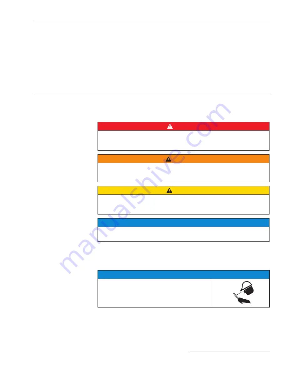
NOTICE

Read this instruction sheet thoroughly and carefully 
before installing or operating your S&C IntelliRupter 
PulseCloser Fault Interrupter.

Replacement 

Instructions  

and Labels

If you need additional copies of this instruction sheet, contact your nearest S&C Sales 
Office, S&C Authorized Distributor, S&C Headquarters, or S&C Electric Canada Ltd.

It is important that any missing, damaged, or faded labels on the equipment be replaced 

immediately. Replacement labels are available by contacting your nearest S&C Sales 
Office, S&C Authorized Distributor, S&C Headquarters, or S&C Electric Canada Ltd.

The seller further warrants to the immediate purchaser or end user that for a 

period of two years from the date of shipment, the software will perform substan-
tially in accordance with the then-current release of specifications if properly used 
in accordance with the procedures described in seller’s instructions. The seller’s 
liability regarding any of the software is expressly limited to exercising its reason-
able efforts in supplying or replacing any media found to be physically defective or 
in correcting defects in the software during the warranty period. The seller does not 
warrant the use of the software will be uninterrupted or error-free.
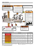
Safety Information

Introduction

Summary of Contents for IntelliRupter PulseCloser

Page 1: ...ng the Base 11 Installing Surge Arresters 11 Connectors Terminal Pads and Conductors 11 Installing Optional Wildlife Protection Feature 12 Installing Communication Module Battery 13 Installing a Radio 13 Installing Modules 14 Installing SCADA Antenna 15 Energizing IntelliRupter Fault Interrupter 16 Substation Power and Communication 17 Operation Establishing a Wi Fi Communication Link with an Inte...

Page 2: ...nate a location where you can easily retrieve and refer to it Proper Application CAUTION The equipment in this publication must be selected for a specific application The application must be within the ratings furnished for the selected equipment Special Warranty Provisions The standard warranty contained in S C s standard conditions of sale as set forth in Price Sheet 150 applies to the IntelliRu...

Page 3: ... S C s website sandc com Or call S C Headquarters at 773 338 1000 in Canada call S C Electric Canada Ltd at 416 249 9171 NOTICE Read this instruction sheet thoroughly and carefully before installing or operating your S C IntelliRupter PulseCloser Fault Interrupter Replacement Instructions and Labels If you need additional copies of this instruction sheet contact your nearest S C Sales Office S C A...

Page 4: ...TA 3221 ONLY when energizing the IntelliRupter fault interrupter indoors in a service center or testing lab Attaching a power supply of other manufacture may cause equipment damage or electric shock WARNING G 9220 IntelliRupter fault interrupter base contains electrical and mechanical parts that can cause injury DO NOT disassemble or remove access panels unless directed by S C Electric Company DO ...

Page 5: ... de energized tested and grounded The Integrated Power Module IPM contains components that can retain a voltage charge for many days after the IntelliRupter fault interrupter has been de energized and can derive a static charge when in close proximity to a high voltage source Voltage levels can be as high as the peak line to ground voltage last applied to the unit Units that have been energized or...

Page 6: ...ly catalog number TA 3221 only After installing both the protection and control module and the communication module as directed on page 14 attach the power supply output cable to the connector on the underside of the IntelliRupter fault interrupter base near the center pole unit open close indicator When finished remove both modules before transport ing the IntelliRupter fault interrupter to the i...

Page 7: ...e and optional external power supply are shipped in water resistant containers placed inside a plastic bag This providesprotectionfromtheelementsduringshipping After receipt they must be stored indoors Storing the communication module control module and optional external power outside will void the warranty 3 Communication modules other than option suffix C0 contain a battery that must be charged ...

Page 8: ...except the lifting brackets Damage to IntelliRupter fault interrupter components such as the Wi Fi antenna or interrupter open closed indicators may result CAUTION Use a crane capable of safely lifting the IntelliRupter fault interrupter Non disconnect style weights 15 kV 27 kV 835 lbs 379 kg 38 kV 865 lbs 392 kg Disconnect style weights 15 kV 27 kV 1010 lbs 458 kg 38 kV 1040 lbs 472 kg Figure 2 L...

Page 9: ...Swing up the two lifting brackets as shown in Figure 1 and in Figure 2 on page 8 Figure 1 for the standard IntelliRupter fault interrupter models and Figure 2 for the compact crossarm models d Attach a suitable sling through the holes in the lifting brackets Lift the unit until the sling is just taut e Unbolt the fault interrupter base from its skid See Figure 3 The 4x4 shipping supports can be le...

Page 10: ...ts Damage to the IntelliRupter fault interrupter may result NOTICE When mounting an IntelliRupter fault interrupter to a wood pole place suitably sized square washers under the nuts To compensate for pole shrinkage and to maintain fastener tightness spring type washers are recommended placed between the square washers and the nuts Also install flat washers under the bolt heads STEP 4 Handle and li...

Page 11: ...urge Arresters NOTICE Surge arresters are required on both sides of an IntelliRupter fault interrupter to protect it from surges beyond its ratings STEP 6 See the Optional Features table in S C Specification Bulletin 766 31 S C IntelliRupter PulseCloser Fault Interrupter for a list of available surge arrester options Mounting provisions for surge arresters are provided If optional surge arresters ...

Page 12: ...ap cover part way over the jumper conductor c Prepare the jumper conductor using established procedures Attach the compression lug or the terminal pad connector Bolt the compression lug or the terminal pad connector to the IntelliRupter fault interrupter terminal pad d Attachthelowerterminal padcover SD 5284 to the interrupter housing Confirm the surge arrester and or integral power module wires l...

Page 13: ...days To install the battery a Loosen battery compartment cover locking screw See Figure 13 b Insert the battery assembly push it most of the way in To connect the battery leads push the connector halves together until the tab on the lower connector half engages the fixed connector half Push battery assembly all the way in See Figure 14 c Inspect the battery compartment gasket Close the battery com...

Page 14: ...ng on a clean dry surface insert the fitting into the module latch While pushing down on the hookstick rotate the handling fitting 90 degrees counterclockwise to open the latch See Figure 16 b Whilestandinginthebucket rotatethehookstick with the module on the end of it 180 degrees lift and insert the module into the bay in the IntelliRupter fault interrupter base For the Communication Module match...

Page 15: ...onal 25 inch fiberglass antenna mounted in position 1 a Remove and retain the hardware attaching the antenna bracket to the IntelliRupter fault interrupter base b Rotate the bracket 180 degrees as viewed from the top c Attachthebrackettothebaseusingthehardware removed in Step 12 a d Loosen the U bolt that attaches the antenna to the bracket Reposition the antenna in the U bolt so it points up and ...

Page 16: ...uffix B3 bracket only mounted in position 2 a Remove and retain the hardware attaching the antenna bracket to the IntelliRupter fault interrupter base b Attachthebrackettotheoppositeendofthebase using the hardware removed in Step 15 a c MounttheYagiantennaoruser suppliedantenna as applicable to the mast using the hardware provided d Attach the antenna cable and secure it with threeplasticcableties...

Page 17: ...vides power to the IntelliRupter fault interrupter when voltage is present and the Alternate input takes over when Preferred input voltage is lost Either input may be used for a single source ac application The voltage ranges for each input are Preferred Input 100 to 259 Vac 50 60 Hz Alternate Input 100 to 259 Vac 50 60 Hz 20 to 60 Vdc or 100 to 360 Vdc When operating in the 100 to 360 Vdc range a...

Page 18: ...can be established To communicate over Wi Fi STEP 1 Open the IntelliLink program click Start Programs S C IntelliLink STEP 2 Select the Choose an IntelliRupter option STEP 3 Select the device name from the drop down list or by typing it or if security keys have not been entered enter the IntelliRupter fault interrupter serial number by using the Configure New IntelliRupter Wi Fi option Then click ...

Page 19: ... See Figure 26 Manually opening the interrupt ers does not require control power it may be performed during an outage If control power is available an elec tronic assist will open all closed poles Manual Lever Close The interrupters can only be closed when control power is available To close the inter rupters using a hookstick first return the OPEN lever to the Ready up position Pull the CLOSE lev...

Page 20: ...OT LINE TAG indicator flashes for second every 2 seconds Any trip in the Hot Line Tag profile will be performed as a three phase trip When the hot line tag is removed the indicator is OFF Manual Ground Trip Block if furnished The ground trip block can be set locally with the hookstick lever or remotely using SCADA or IntelliLink software A ground trip block can only be removed by the method used t...

Page 21: ...ing If the unit is testing the alternate general profile does not become active until the active test sequence has completed Closing profiles and hot line tag profiles are not affected by the position of the GROUND TRIP BLOCK lever SCADA or IntelliLink software commands to change the general profile while using the alternate profile are accepted but the IntelliRupter fault interrupter will not rev...

Page 22: ...en Ready to Close Open to Ready GROUND TRIP BLOCK lever has been moved from Removed to Set Set to Removed Pulsates dim to bright Wi Fi is connected Flashes for second every second Any error state is active Settings Mismatch is active and if configured by user Battery Low Bad or Disconnected Flashes 3 times second on second off every 30 seconds IntelliTeam SG Automatic Restoration System is in the ...

Page 23: ...terminal pads If the IntelliRupter fault interrupter is supplied with the optional wildlife protection feature catalog number suffix W1 or W2 slide the tap cover back far enough to gain access to the terminal pads Remove the upper and lower terminal pad covers to permit the removal of the phase conductors Retain the covers for reuse at the conclusion of the test STEP 2 At each of the six terminal ...

Reviews: