20 S&C Instruction Sheet 765-510
Installing the Wildlife Disks
Before installing the wildlife disks, determine the proper
placement of the disks on the switch blade and contact
insulators.
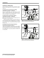
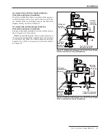
On Upright 14.4-kV Omni-Rupter Switches
(Porcelain and Cypoxy™ Insulators)
Install the wildlife disk to the bottom skirt root of the
insulator on both the blade and contact ends of the switch.
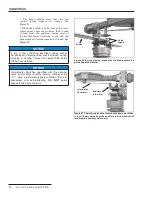
When the wildlife disks are properly installed, the disks
will overlap slightly, as shown in Figure 17.
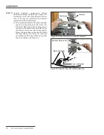
On Upright 25-kV Omni-Rupter Switches
(Porcelain and Cypoxy™ Insulators)
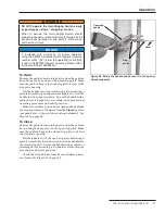
Blade end of the switch
: Install the wildlife disk on the
bottom skirt root of the insulator.
Contact-end of the switch
: Count up two skirts from
the base and install the wildlife disk to the insulator
on the blade-end. When the wildlife disks are installed
properly, they will be at approximately the same height.
See Figure 18.
On Upright 34.5-kV Omni-Rupter Switches
(Porcelain and Cypoxy Insulators)
Count up two skirts from the base and install the wildlife
disks on the third skirt root from the base of the insulator
on both the blade and contact ends of the switch. When
the wildlife disks are properly installed, the disks will
overlap slightly.
Figure 18. Wildlife disk placement on 25-kV Omni-Rupter
Switches, upright mounting configuration.
Contact
end
Blade end
Disks at same
height
Install two skirts
from bottom skirt
root
Insulator
Insulator
Install disk on
bottom skirt root
Figure 17. Wildlife disk placement on 14.4-kV Omni-Rupter
Switches, upright mounting configuration.
Contact end
Blade end
Disks overlap
blade-end over
contact-end
Insulator
Insulator
Install disk on
bottom skirt root
Install disk on
bottom skirt root
Installation


