10
S&C Instruction Sheet 765-500
Installation
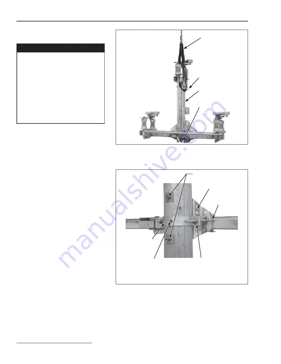
Figure 2. Hoisting Omni-Rupter switch into position for triangular mount-
ing configuration.
Dead-ending
bracket
Vertical support
member
Open slotted hole
Hoisting slings
Figure 3. Typical pole-band attachment detail (upright mounting configu-
ration illustrated).
Pole saddle
Through-bolts
(provided by customer)
¹⁄₂
-inch lag screw
Pole band
J-bolt
¹⁄₄
1
3
stiffening block
Second lag screw installed diagonally opposite on lower corner
of mounting bracket.
Mounting the Switch—Triangular
Mounting Configuration
Ç
WARNING
Lift the switch using the lifting brackets
provided. Do not allow lifting slings to stress
switch parts. Avoid allowing switch to swing
while lifting.
Lifting the switch by the live parts or pole-
unit bases will damage the switch. Rough
handling may cause misalignment of the
blades and contacts.
Failure to lift the switch properly
can result in switch damage, causing
improper operation, arcing or electri-
cal shock.
a. Make sure that the switch is fully closed.
b. Attach lifting slings ONLY to the vertical
switch support member by looping around
the dead-ending bracket and the switch
mounting weldment.
c. Lift switch as shown in Figure 2 until the
lifting slings are just taut.
d. Unbolt the wooden supports from the ship-
ping skid.
e. Slowly and carefully lift the switch to the
proper mounting height.
f. Guide the switch so that the through bolts
projecting from the utility pole slip into the
holes in the switch’s pole-saddle. (The pole-
saddle is provided with a keyhole and an
open slotted-hole for ease of installation.)
g. Securely tighten the through-bolts.
h. Remove the lifting slings from the switch.
Installing the Optional Pole Band
Step 4
Secure the pole-band (optional) to the mounting
bracket on the switch, using the J-bolts pro-
vided. See Figure 3. Two
¹⁄₄
1
3
stiffening
blocks are furnished to be used behind the pole-
band flanges, and underneath the J-bolt nuts.
Lag the pole band to the back side of the pole
through the hole in the center of the band, using
one of the three
¹⁄₂
-inch diameter lag screws
provided. Then, lag the mounting bracket to the
pole using the two remaining
¹⁄₂
-inch lag screws
as shown in Figure 3.
Summary of Contents for Omni-Rupter
Page 28: ...Printed in U S A...


