627-500 20
INSTALLATION
Step 21
Connect the ground bus (or ground pad
on single module assembly) to the system
grounding facility in accordance with the user’s
standard grounding practice. Use a cable not
smaller than 1/0 copper, or equivalent. If the
maximum momentary rating of the switchgear
is to be realized, the equivalent of 750 kc mil
of copper cable is required, in either a single
or multiple connection.
Step 22
M a k e u p t h e m e d i u m - v o l t a g e c a b l e
terminations, following the cable-terminator
manufacturer’s instructions and clearances
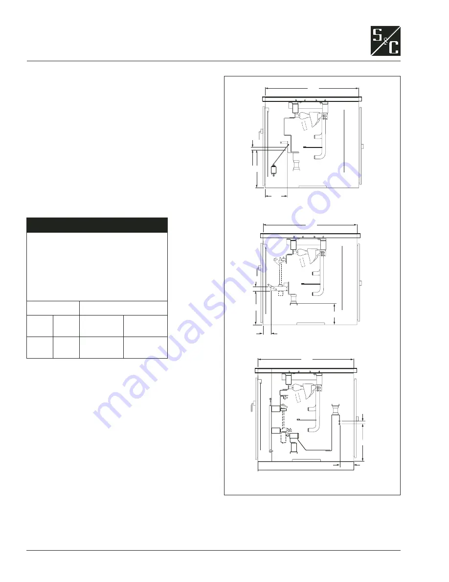
shown in Figure 16.
Ç
WARNING
M a i n t a i n p r o p e r c l e a r a n c e s w h e n
installing cable terminators.
Failure to
maintain proper clearances can result
in a fl ashover, injury, and equipment
damage.
To maintain the rated BIL, the following
minimum
clearances are required:
Rating, kV
Minimum Clearances, Inches
Nom.
BIL
To electrical
ground
To insulating
barriers
13.8
25
95
125
6
7.5
1
2.25
Figure 16. Dimensions and layout of cable terminations.
66
³⁄₄
1
³⁄₄
15
⁷⁄₈
27
1
³⁄₄
66
³⁄₄
5
¹⁄₂
24
⁷⁄₈
15
³⁄₈
1
³⁄₄
66
³⁄₄
9
¹⁄₈
26
¹⁄₄
Detail A,
for all modules with switches only
Detail B,
for
modules with live-front fuse handling
Detail C,
for modules with enhanced
fuse handling


