10
S&C Instruction Sheet 775-510
WARNING
To maintain proper electrical clearance,
make sure the lifting bracket is placed in the
retracted position after the installation .
Failure to do so may increase the risk of
flashover.
Optional extension link assemblies, if supplied, are
shipped assembled to the switch.
Grounding the Switch
Use the following procedure when grounding the Scada-
Mate SD switch:
STEP 8.
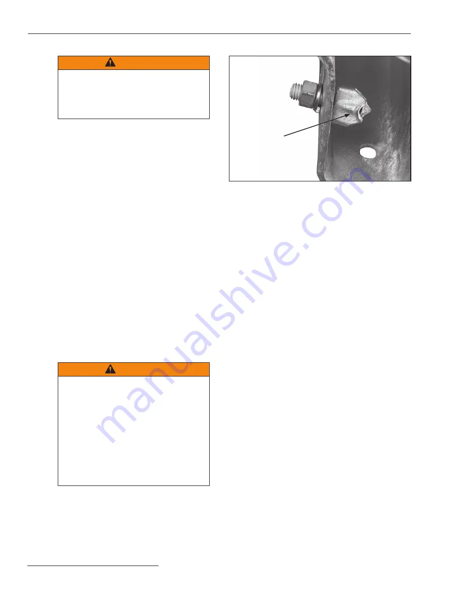
A grounding lug is provided with the switch and
should be installed in the hole on the pole-saddle.
See Figure 6. It is essential to ground the switch
to maintain sensor accuracy, prevent damage to
the control cable from lightning strikes or energy
surges, and to direct any surge path through the
ground, and not through the control unit, where
damage or personal injury may occur. Ground
the switch by solidly connecting the end of a
number 2 AWG wire (or two number 6 AWG
wires, or wires having an equivalent cross-
sectional area) to the grounding lug on the pole-
saddle. See Figure 6.
Insert the ground wire into the ground-lug
hole and tighten the nut on the rear of the pole-
saddle. Connect the ground wire(s) to a suitable
earth ground at the base of the pole and bond
them to the system neutral, if present. Proper
precautions must be taken to ensure the local
earth ground cannot be severed or removed.
WARNING
Before energization and at all times
when energized, the Scada-Mate SD
Switch base and control unit enclosure, if
provided, must be connected to a suitable
earth ground at the base of the pole and
bonded to the system neutral, if present, in
accordance with this instruction sheet . Proper
precautions must be taken to ensure the
local earth ground cannot be severed or
removed .
Failure to observe these instructions can
result in serious personal injury or death.
Figure 6. The grounding lug.
Installation
Grounding lug


