background image

20    S&C Instruction Sheet 461-502

Factory Default Settings

All TripSaver II reclosers are shipped with the factory 
default settings shown below. These settings will protect 
the overhead power line in case an unconfigured TripSaver 
II recloser is installed. Use the configuration kit and the 
S&C TripSaver II® Service Center Configuration Software 
to properly configure a TripSaver II recloser before putting 
it in use.

NOTICE

Failure to properly configure a TripSaver  II recloser 
in accordance with applicable codes and standards 
can result in slow or no response to a fault level and  
miscoordination . Settings should be determined and 
approved by qualified persons who are familiar with 
the principles of selective coordination and system 
protection . 

Default TCC Curve Settings

• 

Initial Trip (1st curve)

: Microprocessor recloser: 

S&C 104 cur ve; minimum trip current: 100 A;  
time multiplier: x1

• 

Open Interval After Initial Trip

: 5 seconds

• 

Sequence Coordination

 (disabled by default):  

Microprocessor recloser: S&C 133 curve; minimum trip 
current: 100 A; time multiplier: 2

• 

Coordination Reset Time

: 120 seconds

• 

Test 1 (2nd curve)

: Microprocessor recloser: S&C 104 

curve; minimum trip current: 100 A; time multiplier: x1

• 

Open Interval After Test 1

: 5 seconds

• 

Test 2 (3rd curve)

: Microprocessor recloser: S&C 133 

curve; minimum trip current: 100 A; time multiplier: x2

• 

Open Interval After Test 2

: 5 seconds

• 

Test 3 (4th curve)

: Microprocessor recloser: S&C 133 

curve; minimum trip current: 100 A; time multiplier: x2

• 

Sequence Reset Time

: 15 seconds

Default NR Curve Settings

• 

Standard NR: Microprocessor recloser

: Definite 

time; minimum trip current: 100 A; time: 0 seconds 

• 

Post-Fault Wakeup NR Curve

:


Microprocessor 

recloser: definite time; minimum trip current: 100 A; 
time: 0 seconds

• 

Cold Wakeup NR Curve

: Microprocessor recloser: 

definite time; minimum trip current: 100 A; time:  
0 seconds

Default LCD Screen Settings

• 

Screen to display when recloser is dropped-open

Primary Normal 

screen

• 

Language

: English

• 

Normal screen

Primary Normal

 screen

• 

Number of times the display screen sequence 
repeats

: 2 times

• 

Duration of each display screen item

: 3 seconds

• 

Display screen items

Primary Normal 

screen; 

load current; last fault magnitude; number of open  
operations; remaining contact wear in %; LCD screen 
temperature; software versions

Default Communications Settings

• 

Communication Mode

:

 Non-Gateway

 mode

• 

Side-magnet Radio Enabling Function

: Enabled

Default Local Manual Open Settings 

• 

Function

: Disabled

Operation

Summary of Contents for TripSaver II

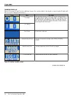
Page 1: ...s Mounting 13 Operation If the TripSaver II Recloser Has Dropped Open 14 If Line Work Is to Be Performed Downstream of a TripSaver II Recloser 14 Display Screen 15 Additional Screens 18 Factory Defaul...
Page 2: ...edures in this instruction sheet is available at sandc com videos install ts2 The goal of the video is to provide a clear and simple visual reference In no way is the video meant as a complete replace...

Page 3: ...vided Type XS Fuse Cutout mounting See the example in Figure 1 An example of an earlier production S C Type XS Fuse Cutout mounting is shown in Figure 2 The warranty set forth in S C Price Sheet 150 d...

Page 4: ...ns are not followed NOTICE NOTICE identifies important procedures or requirements that can result in product or property damage if instructions are not followed Following Safety Instructions If you do...

Page 5: ...mber DANGER TripSaver II may be energized from either side and in any position Always consider all parts live until de energized tested and grounded G 9473 E G 9473 E DANGER TripSaver II may be energi...

Page 6: ...ctric shock and death DANGER The TripSaver II Cutout Mounted Recloser operates at high voltage Failure to observe these precautions will result in serious personal injury or death Some of these precau...

Page 7: ...pany in all instances of loss and or damage Handling NOTICE DO NOT drop a TripSaver II recloser or subject any of its parts to undue stress during installation Only remove a TripSaver II recloser from...

Page 8: ...provide maximum ease of operation then securely tighten the carriage bolt nut STEP 2 Make electrical connections to the mounting If aluminum conductors are used be sure to wire brushthemandthenapplya...

Page 9: ...s used rotate the hotstick counterclockwise 180 to disengage it Alternately insert the TripSaver II recloser into a 110 kV BIL rated mounting with gloved hands as shown in Figures 4b and 4c Guide the...

Page 10: ...ndling Tool or a distribution prong to a short hotstick Insert the curled prong of the Talon tool or the distribution prong into the lifting eye of the trunnion and raise the TripSaver II recloser int...

Page 11: ...TripSaver II recloser Insert the straight prong of an S C Talon Handling Tool or a distribution prong into the pull ring b To close a TripSaver II recloser using an extendo stick stand between 6 to 10...

Page 12: ...on the lever must align with the label on the lower body See Figure 11 and Figure 12 The operational status of a TripSaver II recloser is indicated on a nonvolatile liquid crystal display LCD screen...

Page 13: ...option O The factory default is 5 seconds The vacuum interrupter resets 2 seconds after the TripSaver II recloser drops open If a temporary fault is cleared before the TripSaver II recloser reaches th...

Page 14: ...II recloser STEP 1 Place the MODE SELECTOR lever in the NR position Rotate the MODE SELECTOR lever downward using the straight prong of a Talon Handling Tool or a distribution prong as shown in Figure...

Page 15: ...display screen supports messaging in English Spanish Portuguese French Chinese and Arabic The display shows the Primary Normal screen most of the time Additional display screens are available by togg...

Page 16: ...the end of the operating sequence or when the MODE SELECTOR lever changes position The Overload symbol will not be updated when the recloser drops open because of an over load and the Service Soon sym...

Page 17: ...m interrupter contact wear is shown See Figure 22 LCD Screen Temperature The LCD screen temperature is shown in degrees Celsius See Figure 23 Sectionalizing Mode Counts This screen displays the preset...

Page 18: ...mber of Open operations at the upper right corner and remaining contact wear in bar chart format at the bottom of the screen A full blue bar indicates 100 remaining contact wear The blue bar shortens...

Page 19: ...short name for the Test 3 curve 4th TCC curve is displayed This screen is automatically skipped if Test 3 operation is disabled Interrupting Rating The interrupter rating of the recloser in kA is dis...

Page 20: ...ssor recloser S C 104 curve minimum trip current 100 A time multiplier x1 Open Interval After Test 1 5 seconds Test 2 3rd curve Microprocessor recloser S C 133 curve minimum trip current 100 A time mu...

Page 21: ...ould be felt STEP 2 Fasten the Loadbuster tool to an S C Universal Pole not less than 6 feet 183 cm long 8 feet 244 cm for catalog number 5400R3 with the frame of the tool in line with the pole As sho...

Page 22: ...ment of a Loadbuster tool in this position is difficult and may result in an improper opening operation leading to arcing faults equipment damage serious injury or death Figure 28 A correct fastening...

Page 23: ...o open the TripSaver II recloser extends the Loadbuster tool and charges an internal spring At a predetermined point in the opening stroke a trigger inside the tool trips releasing the charged spring...

Page 24: ...tended To perform this operation easily and smoothly always roll the Loadbuster tool so that it rotates in an upward direction STEP 5 To reset the Loadbuster tool for the next operation hold it as sho...

Page 25: ...times within Y second window 10 second Cancellation window 20 second Walk Away window Recloser breaks load and drops open Triggering condition not met Any lever movement Triggering condition met LMO...

Page 26: ...e operating lever position at the time the TripSaver II recloser trips Figures 36 through 39 show how new LCD screens appear LMO events will be recorded in the Event log When there is not enough charg...

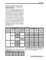
Page 27: ...is waking up from when being closed into its mounting and whether the Temporary Auto mode has been disabled under the R NR Functions menu Table 1 Active TCC Curve when TripSaver II Recloser is in R NR...

Page 28: ...e TripSaver II recloser and the communications gateway cabinet See Figure 41 A gang operation can be initiated when one TripSaver II recloser opens in response to an overcurrent event when the Local M...

Page 29: ...e using a battery will reset the recloser s vacuum interrupter but NOT the drop open mechanism This state can be confirmed if the recloser s LCD screen reads VI Open but the recloser appears closed Th...

Page 30: ...he display screens If the battery is removed before the refresh of any screen is completed the LCD image will freeze at the point the battery was removed End of Interrupting Capability and Service Now...

Page 31: ...mechanism using the procedure described on page 29 If a TripSaver II recloser still cannot be closed into the mounting this may indicate that the recloser is in an operational Error state The TripSave...

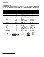
Page 32: ...na ENACOM C 22979 March 22 2019 Australia New Zealand ACME Declaration of Conformity March 16 2018 Bolivia ATT ATT DJ RA H TL LP 282 1018 June 4 2018 Brazil ANATEL 02523 18 05925 April 18 2018 Canada...

Page 33: ...017 Colombia CRC 2018518582 May 22 2018 Costa Rica SUTEL 03966 SUTEL DGA 2018 May 23 2018 Ecuador ARCOTEL ARCOTEL NRH 2018 000147 May 21 2018 El Salvador SIGET No DBP 057 2018 June 4 2018 Grenada NTRC...

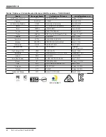
Page 34: ...Rica SUTEL 03968 SUTEL DGA 2018 May 23 2018 Ecuador ARCOTEL ARCOTEL NRH 2018 000146 May 21 2018 El Salvador SIGET No DBP 057 2018 June 4 2018 European Union CE TSII DONGLE2 Compliant DoC May 6 2019 Do...

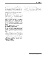
Page 35: ...erence in which case the user will be required to correct the interference at his own expense Canada ISED Innovation Science Economic Development Canada This device complies with Industry Canada licen...

Page 36: ...prejudicial e n o pode causar interfer ncia em sistemas devidamente autorizados Este produto est homologado pela ANATEL de acordo com os procedimentos regulamentados pela Resolu o 242 2000 e atende ao...

Reviews: