S&C Instruction Sheet 695-510
9
Components
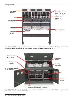
S&C Vista SD Underground Distribution Switchgear features load-interrupter switches and
microprocessor-controlled fault interrupters for the switching and protection of 600-ampere
main feeders and 200- or 600-ampere taps, laterals, and sub-loops. These elbow-connected
components are encapsulated in an environmentally friendly solid-dielectric insulating
material. Vista SD switchgear is available in ratings through 29 kV and 16 kA symmetrical
interrupting. See Figures 4 and 5 on pages 10 and 11.
S&C Vista SD Underground Distribution Switchgear is considerably smaller than traditional
air-insulated gear; it can be installed exactly where it’s needed. It’s completely submersible
and thus suitable for installation in subsurface vaults subject to flooding. Single-way Vista
SD assemblies are ideally suited for application on the primary side of network transformers.
Multi-way assemblies—from three to six load-interrupter switches or fault interrupters—are
also available.
S&C Visi-Gap load-interrupter switches use a vacuum interrupter in series with a manually
operated two-position isolating disconnect for three-pole live switching of 600-ampere three-
phase circuits. Load-interrupter switches comply with IEEE Standard 1247 and IEC Standard
62271-103. They feature an easy-to-operate manual operating mechanism.
S&C Visi-Gap fault interrupters use a vacuum interrupter in series with a manually operated
two-position isolating disconnect for three-pole load switching of 200- or 600-ampere circuits
and fault interrupting through 16 kA symmetrical at 17.5 kV and through 12.5 kA symmetrical at
29 kV. Fault interrupters comply with both IEEE Standard C37.60 and IEC Standard 62271-111.
Load-interrupter switches and fault interrupters can be directly opened and closed
using the manual handle furnished; they can also be operated remotely using a piece
of rope attached to the manual handle or by a user-furnished universal pole of the
appropriate length, equipped with a standard fitting. Opening and closing speed of the vacuum
interrupters is not dependent upon the speed with which the handle is moved. Operating shafts
are padlockable in either position.
Factory-installed and wired motor operators, to facilitate remote power operation
of load-interrupter switches and fault interrupters, are optionally available. They can
be decoupled from the operating mechanisms to permit testing without changing the
positions of the switches or fault interrupters. The motor operators require a user-furnished 100-
240 Vac 50/60-Hz control power source; they’re controlled from a hand-held, cable-connected
portable remote control pendant.
Easy-to-follow mimic bus and indicators on the front of the switchgear convey the positions
of the load-interrupter switches and fault interrupters (and their isolating disconnects), and
whether a fault interrupter has tripped on a fault. The default color scheme is green for the
OPEN/RESET indicator and red for the CLOSED indicator. These colors will be reversed (i.e.,
green for the CLOSED indicator and red for the OPEN/RESET indicator) if catalog number
sffix “-J1” has been specified.
Large viewing windows provide a clear view of the isolating disconnects, allowing operating
personnel to easily confirm the positions of the load-interrupter switches and fault interrupters.
Terminals are equipped with field-replaceable 600-ampere rated bushing adapters. Fault
interrupters may be optionally equipped with 200-ampere bushing-well adapters in lieu of
600-ampere bushing adapters. Bushing and bushing-well adapter interfaces conform to IEEE
Standard 386 and accept all standard insulated connectors and inserts recognized by this
standard.
The self-powered overcurrent control can be programmed using a personal computer
connected to the control through an adapter cable. The control features a variety of fuse
and relay time-current characteristic (TCC) curves that comply with IEEE Standard C37.112.


