


The
lower display area presents the numeric data associated with the
two bearing pointers. This includes the nav source, bearing and
distance (if available). The upper section of this area also contains a
display of the marker beacon lights and the GPS annunciators, if
configured.
Indicators
Several different symbols, or
indicators, are used in each of the
display areas. These are described below: The white
symbol is the
“lubber line,” pointing to the magnetic heading. It is always at the top
of the display.
The amber
symbol is the heading bug. This can be set by rotating
the Heading Select knob or pressing [SYNC]. When the display has
been set to 70-degree ARC mode using the [VUE] button, it is
possible for the heading bug to be positioned off the screen. When
this happens, the heading bug “parks” at the side of the screen
nearest to its actual position, with the symbol displayed smaller than
normal and close to the edge of the screen.
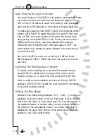
The
symbol is the course pointer. By rotating the Course Select
knob, you can set the course pointer to the desired course to a VOR
nav source. When a long-range nav source is selected, the course
pointer can automatically rotate to the desired track being sent by
the nav source (i.e. “Auto-Slew”). The Course Deviation Indicator,
or “CDI” (also known as a deviation bar or “D-bar”) is the movable
center section of the course pointer which depicts deviation to the
left or right of course. The CDI is also repeated at the bottom of the
display. Note that the center CDI is not visible when the map display is
enabled or if it is disabled in the [SHFT]>[NAV] function. When the
display is in 70-degree ARC mode, it is possible for the head of the
course pointer to be positioned off the screen. When this happens,
the course pointer “parks” at the side of the screen nearest to its
actual position, with the symbol displayed smaller than normal and
close to the edge of the screen.
2 - 2
2
Display Overview
C H A P T E R
Summary of Contents for SN3308
Page 1: ......
Page 15: ...Welcome to the SN3308 1 C H A P T E R...
Page 19: ...Display Overview 2 C H A P T E R...
Page 24: ...Operational Basics 3 C H A P T E R...
Page 36: ...Button Operations 4 C H A P T E R...
Page 57: ...Enhanced Moving Map Features 5 C H A P T E R...
Page 70: ...Getting the Most From Your SN3308 6 C H A P T E R...
Page 76: ...Flags Abnormal Conditions and Messages 7 C H A P T E R...
Page 85: ...Technical Specifications and Operating Limits 8 C H A P T E R...
Page 87: ...Installation Information 9 C H A P T E R...
Page 89: ...Technology of the SN3308 1 A P P E N D I X...
Page 92: ...Illustrations 2 A P P E N D I X...
Page 98: ...Limited Parts Labor Warranty 1 w A R R A N T Y...


