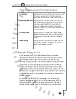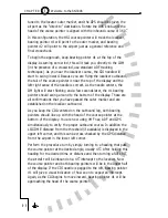
Getting Started – Example
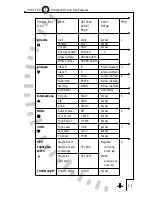
The Factory Default SN3308 map memories are set up as follows:
S: Empty
1: Flight plan only with courselines
2: Flight plan and paved civil airports over 3500' in length
3: Flight plan and HI and LO VORs
4: Empty
To get started, we recommend you try some operations on the
ground. Ensure that your GPS receiver is operating, and enter a flight
plan using its normal procedures. You can use the simulator mode of
your GPS receiver if it has one, or if it does not, make sure the flight
plan you enter is near the airport where you are located.
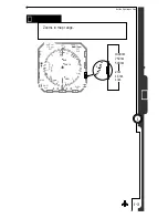
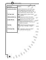
Press [MAP] until “1” shows at the top of the map status bar. With
this setting, you should see the waypoint icon
next to the [MAP]
key, indicating that flight plan waypoints are enabled on the display.
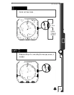
Use the [
] or [
] key to adjust the display range, which is the
number of miles between the symbolic airplane and the outer
compass ring.
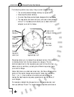
You should see your GPS flight plan on the display. The active leg and
waypoint will be shown in magenta and the other waypoints and
courselines will be shown in white.
5 - 6
5
Enhanced Moving Map Features
C H A P T E R
1
Prohibited airspace is shown in Red and cannot be turned off on the
map display.
2
Flight plan waypoints can be selected to show as facility icons (such as
VOR or INT icons) or to show as waypoint icons only
using map
setup page 8. Most RS-232 GPS receivers are limited to showing
waypoint icons only.
3
Runways below a selectable minimum length may be masked from the
display by pressing the MIN LEN softkey. This parameter may be set
to 2000', 2500', 3000', 3500', 4500', 5500', 6500' or ALL.
4
TACAN is a single setting which will affect all of the map memories.
This can be set from within any map memory and will affect all map
displays.
Summary of Contents for SN3308
Page 1: ......
Page 15: ...Welcome to the SN3308 1 C H A P T E R...
Page 19: ...Display Overview 2 C H A P T E R...
Page 24: ...Operational Basics 3 C H A P T E R...
Page 36: ...Button Operations 4 C H A P T E R...
Page 57: ...Enhanced Moving Map Features 5 C H A P T E R...
Page 70: ...Getting the Most From Your SN3308 6 C H A P T E R...
Page 76: ...Flags Abnormal Conditions and Messages 7 C H A P T E R...
Page 85: ...Technical Specifications and Operating Limits 8 C H A P T E R...
Page 87: ...Installation Information 9 C H A P T E R...
Page 89: ...Technology of the SN3308 1 A P P E N D I X...
Page 92: ...Illustrations 2 A P P E N D I X...
Page 98: ...Limited Parts Labor Warranty 1 w A R R A N T Y...

