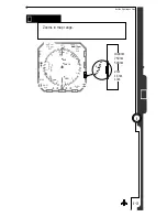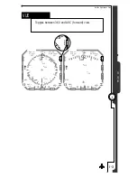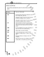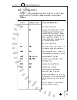
Set the map range to 30 nm, and press [MAP] so that “2” is displayed.
The display should show your flight plan as above, overlaid with local
airports with runways over 3500'. Note that the airport icon shows
on the map status bar indicating airports are being displayed, and
that on-screen airports are shown in
amber. The amber color
indicates that the source of the airport data is coming from the
internal database. The flight plan information, coming from the GPS
receiver, is displayed in magenta and white.
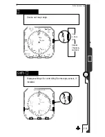
Lower the map range to 10nm, and notice that as the display zooms
in any airport shown will change from the airport icon into a runway
(or multiple runways). Below 7nm the runway numbers will also be
added so that as you zoom in you can plainly see the airport
identifier, runways, and runway numbers. During flight, the display
will rotate and update with the aircraft in real-time.
Press [MAP] to change to memory 3. Notice that airports will be
removed and instead local LO and HI VORs will be shown in Amber.
Note that on the map status bar the airport icon will be removed and
the VOR icon will display, indicating that VORs are enabled.
Pressing [MAP] again will skip memory 4, because it is empty, and
jump directly to MAP OFF. All the map information will be removed
from the screen. Further presses of the [MAP] key will again cycle
through map memories 1, 2 and 3 and then back to MAP OFF.
Map Setup
We are about to change what is displayed on the map, using memory
1 as the
baseline. Start by pressing [MAP] until “1” shows at the top
of the map status bar.
Press [SHFT]>[MAP] to enter Map Setup. All settings in memory 1
are copied to S (the scratchpad memory), and you can now make
non-permanent changes with the softkeys. Notice that
you are editing
memory S. If you want to save these changes back into memory 1,
you can use the COPY function, described on page 5-9.
5 - 7
5
Enhanced Moving Map Features
C H A P T E R
Summary of Contents for SN3308
Page 1: ......
Page 15: ...Welcome to the SN3308 1 C H A P T E R...
Page 19: ...Display Overview 2 C H A P T E R...
Page 24: ...Operational Basics 3 C H A P T E R...
Page 36: ...Button Operations 4 C H A P T E R...
Page 57: ...Enhanced Moving Map Features 5 C H A P T E R...
Page 70: ...Getting the Most From Your SN3308 6 C H A P T E R...
Page 76: ...Flags Abnormal Conditions and Messages 7 C H A P T E R...
Page 85: ...Technical Specifications and Operating Limits 8 C H A P T E R...
Page 87: ...Installation Information 9 C H A P T E R...
Page 89: ...Technology of the SN3308 1 A P P E N D I X...
Page 92: ...Illustrations 2 A P P E N D I X...
Page 98: ...Limited Parts Labor Warranty 1 w A R R A N T Y...

