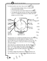
tuned to the locator outer marker, and the GPS should be given the
airport as the “direct-to” destination. Rotate the OBS knob until the
head of the course pointer is aligned with the inbound course of 360˚.
In this configuration, the HSI course pointer will track the localizer,
bearing pointer #1 will point to the outer marker, and bearing
pointer #2 will point to the airport just as a general reference and
final cross-check.
To begin the approach, keep bearing pointer #1 at the top of the
display. Assuming zero wind, this will track you directly to the LOM
(in the presence of a crosswind, use standard ADF tracking
techniques). As you near the localizer course, the CDI needle will
start to swing inward. Because you are flying the localizer outbound,
the tail of the course pointer is near the top of the display and the
left-right sense of the needle is correct. As the needle centers, the
OM light will start flashing and a few seconds later, the #1 bearing
pointer should swing around to the bottom of the display. These are
all confirmations that you have passed the outer marker and are
established on the localizer outbound.
As you keep the CDI centered on the outbound leg, both bearing
pointers should line up with the head of the course pointer at the
bottom of the display. You are now using VHF nav, ADF and GPS
simultaneously to verify the proper outbound course. In addition the
LOC-DME distance from the threshold (if available) is displayed in the
upper left corner, and this can be cross-checked by the GPS distance
from the airport in the lower left corner.
Perform the procedure turn by simply turning to a heading that puts
the course pointer at the desired angle, usually 45˚. After holding this
heading for the desired time or distance and then turning a full 180˚,
the aircraft will be inbound on a 45˚ intercept to the localizer. Now
the course pointer and both bearing pointers will be in the upper half
of the display. If the CDI needle is pegged to the left, bearing pointer
#1 will give a visual indication of how soon to expect an intercept.
Again, as the CDI begins to move inward, bearing pointer #1 will be
approaching the head of the course pointer.
6 - 4
6
Welcome to the SN3308
C H A P T E R
Summary of Contents for SN3308
Page 1: ......
Page 15: ...Welcome to the SN3308 1 C H A P T E R...
Page 19: ...Display Overview 2 C H A P T E R...
Page 24: ...Operational Basics 3 C H A P T E R...
Page 36: ...Button Operations 4 C H A P T E R...
Page 57: ...Enhanced Moving Map Features 5 C H A P T E R...
Page 70: ...Getting the Most From Your SN3308 6 C H A P T E R...
Page 76: ...Flags Abnormal Conditions and Messages 7 C H A P T E R...
Page 85: ...Technical Specifications and Operating Limits 8 C H A P T E R...
Page 87: ...Installation Information 9 C H A P T E R...
Page 89: ...Technology of the SN3308 1 A P P E N D I X...
Page 92: ...Illustrations 2 A P P E N D I X...
Page 98: ...Limited Parts Labor Warranty 1 w A R R A N T Y...


