82002-PG-F
ST3400 TAWS/RMI PILOT’S GUIDE
PAGE 44
Bearing Pointers
The RMI display can show two independent bearing pointers - primary and
secondary. Each pointer is fed from an individually selected navigation
receiver source.
The primary pointer is displayed as a single needle. The secondary pointer
is displayed as a double needle. The head of each bearing pointer indicates
the bearing
to
the navigation source and the tail of each pointer indicates
the bearing
from
the navigation source.
BRG Pointer No 1
.
The single needle pointer displays bearing to the
current selected navigation source. Press [
BRG 1
] to turn BRG1 on/off.
HOLD [
BRG 1
] to activate the selection menu. Bearing source selection
includes all installed navigation receivers. To exit the menu, press [
MENU
OFF
] softkey.
BRG Pointer No 2
. The double needle pointer displays bearing to the
current selected navigation source. Press [
BRG 2
] to turn BRG2 on/off.
HOLD [
BRG 2
] to activate the selection menu. Bearing source selection
includes all installed navigation receivers. To exit the menu, press [
MENU
OFF
] softkey.
The color of each bearing pointer, and its associated numeric display,
provide the following color-coding when on-side:
ADF:
Magenta
GPS:
Cyan
VOR:
Green
The color of each bearing pointer, and its associated numeric display, is
yellow
for any cross-side source.
The digital numeric bearing to the navigation source of the bearing pointer
is displayed at the bottom of the screen. When the data is invalid “---“ is
displayed and the associated bearing pointer is removed from the screen.
The selected bearing pointer name is displayed above the numeric bearing
display.
Note. Certain ADF receivers may not supply an “invalid” signal. In these
cases, the receiver will “park” the needle, usually 90
q
to the right of the
lubber line, when no signal is being received. See the Pilot’s Guide for
your navigation receiver to determine its capability during “No-signal”
operation.
82002-PG-F
ST3400 TAWS/RMI PILOT’S GUIDE
PAGE 45
CHAPTER 10. TERRAIN ALERTS
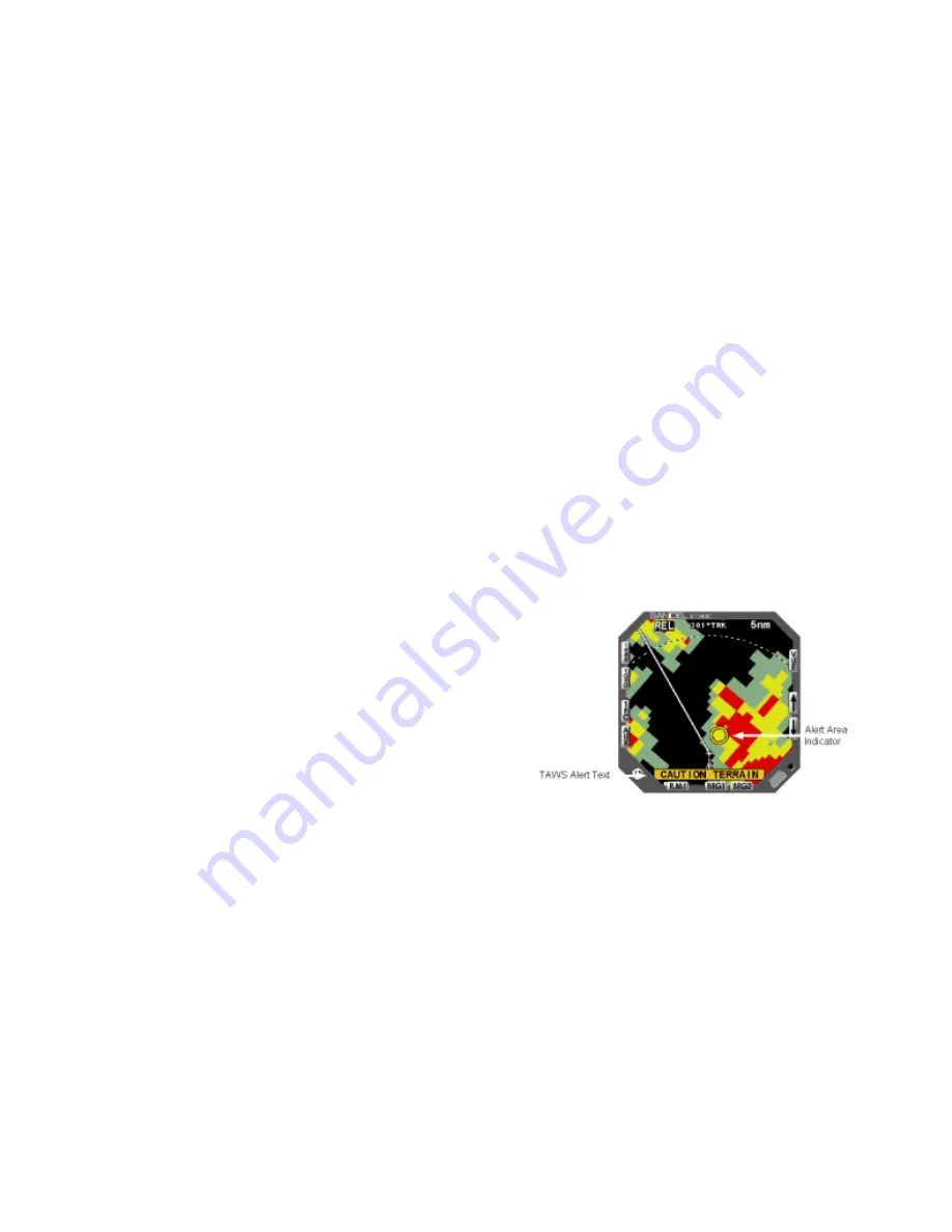
The FLTA Alert Area is an internal computation that covers an area mostly
in front of and somewhat to the side of the aircraft.
Through sophisticated look-ahead algorithms, alerts are generated if terrain
or an obstacle conflict with the flight path angle of the aircraft.
Range and altitude of the aircraft are computed along the projected flight
path at one-second intervals. The projected range is based on current
aircraft location and the aircraft’s ground speed. The projected altitude is
based on current aircraft altitude and the aircraft’s vertical speed. Within
the Alert Area the aircraft’s projected flight path and each terrain cell’s
elevation are compared to check for terrain threats. This area of potential
conflict projects forward and to the sides of the aircraft. In turning flight,
the covered alert area grows in the direction of the turn.
During enroute operations, a caution typically occurs approximately 60
seconds ahead of the terrain conflict. A caution will turn into a warning if
evasive action is not taken. An audible and visual alert will be produced at
the closest cell in which a threat is detected.
An AMBER annunciator indicates CAUTION


