background image

Off

Off

Grid

Grid

Inverter

Inverter

20

Before electrical connection, please make sure that the AC side and DC

side are uncharged!

Ask for correct grounding, using appropriate conductor and providing

necessary short-circuit protection to ensure safe operation.

Please don’t turn on any breakers before all the equipment unfinished
connection.

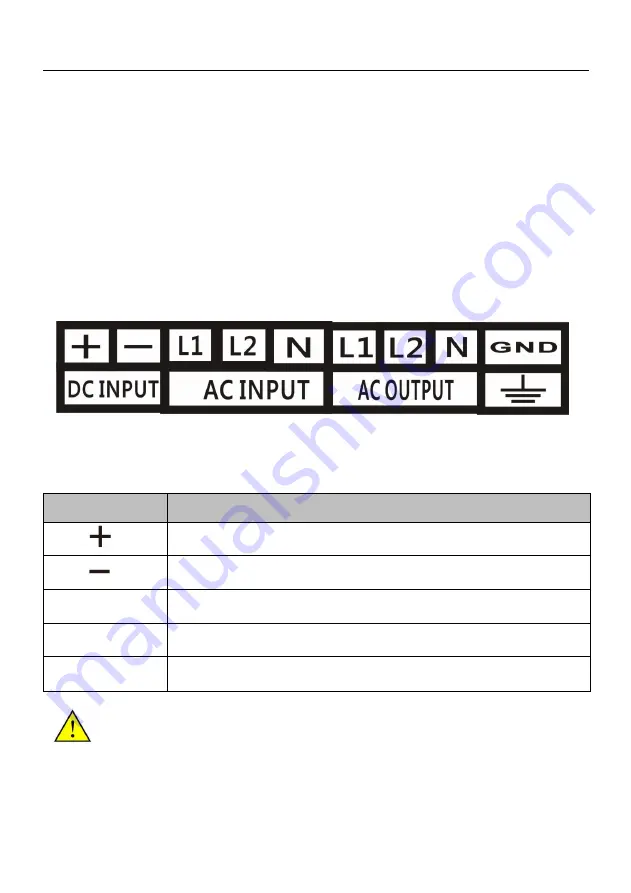
6.1 Connecting Terminals of inverter

The input and output terminals are installed in the bottom of the inverter and
include DC side input terminals and AC side output terminals.

Figure6-1 Connection terminals on inverter

Table 6-1 Terminals Description

Terminals

Description

Battery positive input terminals

Battery negative input terminals

L1,L2, N

AC Input terminals, connect with AC grid

L1,L2, N

AC Output terminals, connect with AC load

PE

Earth Wire

Warning

The positive and the negative mustn't be misconnected.

Summary of Contents for SDP-30KW

Page 1: ...ions instructions in in the the manual manual and and machine machine properly properly keep keep this this manual manual well well Before Before not not read read all all safety safety and and operat...

Page 2: ...escription 10 2 3 1 Working Principl 10 2 3 2 Derating 11 2 3 3 Product Feature 12 3 Inverter Unpacking 13 3 1 Unpacking Check 13 3 2 Identify Inverter 13 4 Installation Procedure 14 4 1 Prepare Insta...

Page 3: ...uctions 21 7 1 LCD display description 21 7 2 Indicator of LED light function 21 7 3 Fault Code 22 7 4 LCD Display Interface Overview 22 8 LCD Panel Operating Instructions 23 9 Malfunction and Trouble...

Page 4: ...e inverter type alone Target Reader This manual apples to the inverter installation person and professional engineering technology person of operation and LCD interface operation person Use the Manual...

Page 5: ...s SAA mark The inverter complies with the requirements of the applicable Australia guidelines Safety Symbol Meaning Danger If ignore the security warning it may lead to serious accidents of injuries W...

Page 6: ...onal technical person Receive special training Complete to read this manual and master related safety attentions of operation Any damage to the equipment caused due to failure to comply with the descr...

Page 7: ...he solar cell arrays are covered with opaque materials otherwise the solar cell arrays will generate high voltage causing person casualties Electrical connections Warning All the operating and wiring...

Page 8: ...nnection Danger Please don t connected any terminal connectors under inverter charged state Please don t open the cover plate under inverter charged state Notice When the inverter is running only LCD...

Page 9: ...reas with traffic inconveniences in the mountains pastoral border island and other areas without electricity It has the main advantages of high quality sine wave AC output microcomputer control humann...

Page 10: ...on through LCD display screen also can set some function and parameters of converter 2 Lock The lock of converter used to open and lock 3 PG Cable Glands The input wire and output wire through this ca...

Page 11: ...ial problems When the operating environment temperature and altitude are too high both can cause inverter derate operation Environment temperature too high Inverter temperature derating curves in belo...

Page 12: ...ss than 1 The DC input voltage range can be set over voltage point under voltage point over voltage recovery point under voltage recovery point and under voltage recovery time all can be set via the L...

Page 13: ...verter Unpacking 3 1 Unpacking Check The product has been tested and checked carefully before transportation but damage may be caused during transportation therefore the product should also be checked...

Page 14: ...tion Procedure 4 1 Prepare Installation Tools Before installation need to prepare first Inverter installation and wire installation will need the following tools You also can choose the right tools ac...

Page 15: ...wires installation Installation steps Installation instruction Reference chapters 1 Before installation check whether the inverter is in good condition Whether the product fittings are complete Whethe...

Page 16: ...ion do not install the inverter in the case closed otherwise the inverter will not work properly Inverter protection level is IP20 can be installed indoor when the inverter is installed indoor should...

Page 17: ...a short circuit on load 5 3 2 DC input cable must be through from the DC input terminals correctly connect to the positive and negative pole of the machine attention can t be reversed 5 3 3 Absolutel...

Page 18: ...it breaker firstly then turn on start switch Make the inverter starting load can effectively avoid the damage of large inrush current to the machine 5 3 14 Don t connect ground wire PE of cabinet and...

Page 19: ...powered on don t connect or disconnect the wires and terminals 5 4 7 After connect all wires please must be carefully check voltage value positive and negative pole are consistency grounding is well...

Page 20: ...connection 6 1 Connecting Terminals of inverter The input and output terminals are installed in the bottom of the inverter and include DC side input terminals and AC side output terminals Figure6 1 C...

Page 21: ...dicator Direction LED Indicator Name Color Instructions BPS AC bypass priority mode it indicates the AC grid input condition INV Running light Green Battery priority mode it indicates the battery supp...

Page 22: ...under voltage OVER LOAD Current over load MOD Module error OUTErr Output voltage unbalance This error only for 3 phase output single phase output without this error display 7 4 LCD Display Interface O...

Page 23: ...T Total generated amounts W KWH Generated amounts Inv State Inverter working state DCU OVER DC over voltage DCU UNDER DC under voltage OVER LOAD Over load MOD Module error Fault display N indicate no...

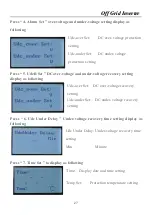
Page 24: ...Info Running state display 2 Inv Start Mode Inverter Start mode 3 Work Modes Working Mode 4 Parameter Set System parameter setting Press 2 Inv Start Mode display as following 1 Voltage Constant freque...

Page 25: ...ly for professionals operation the non professionals can t change parameters otherwise you will undertake all damages caused by privately settings 1 Freq Set Frequency setting 2 VIout Set Output volta...

Page 26: ...s following Vout Set Output voltage setting Iout Max Set Output current setting Noticed Output Max Current default is overload protection current value it can t be set Output voltage set not more than...

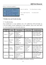
Page 27: ...et DC over voltage and under voltage recovery setting display as following Udc over Set DC over voltage recovery setting Udc under Set DC under voltage recovery setting Press 6 Udc Under Delay Under v...

Page 28: ...em restart automatic Check battery output voltage ensure the output voltage within arrange of inverter State 02 DC input Over voltage Inverter stop working malfunction disappear system restart automat...

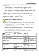
Page 29: ...with electricity Check humidity and dust of inverter surrounding environment if have too much dust clean the inverter Check the inverter cable connection is loose if loose tightening again according t...

Page 30: ...Within warranty time when inverter meets all the installation environment and using conditions also operation correctly if the inverter have damage or accident happens please inform our company after...

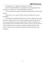
Page 31: ...ts which do not influence the energy production Claims that go beyond the rights cited in the warranty conditions in particular claims for compensation for direct or indirect damages arising from the...

Page 32: ...r load 3 Nonlinear load Dynamic Response 0 to 100 load 5 50ms load 0 100 Running mode Working continuously Electrical insulation properties 2000Vac 1 Minute Protection Function Overload Ability 150 5...

Reviews: