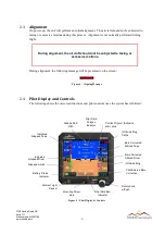
background image


16 


3700 Osuna Road NE 
Suite 711 
Albuquerque, NM 87109 
www.sandia.aero 


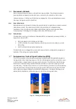
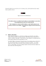
If the battery fails the power-on self-test (or is in a heating cycle), it will be Red-X’ed and no backup 
battery capability will exist: 


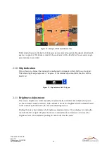
Figure 20 - Battery Not Available Indication 


If the battery status icon is Red-X’ed, the battery is not available for use and loss 

of aircraft power will result in the unit turning off. 

Prior to departure or entry into IFR conditions, verify that the battery is not 

faulted (no red-X over the battery icon), and that a charge level of at least 80% is 

shown. 


3.6


Battery Duration 

Battery duration is dependent on several factors; including age of the battery pack, display 
intensity setting and ambient operating temperature. With a healthy battery, a minimum of 30 
minutes of operation is guaranteed.  Typical durations when operating at room temperature and a 
reduced display brightness will be approximately 2 hours. 

Note that the charge level indicated is an approximation of the remaining capacity of the battery, 
and will dynamically adjust based on operating environment and conditions.   For example, 
diming of the display will extend the battery duration, and thus increase the percent charge 
shown.  Correspondingly, increasing the display brightness will reduce the battery duration and 
thus decrease the percent charge shown.


Summary of Contents for SAI-340A

Page 1: ...3700 Osuna Road NE Suite 711 Albuquerque NM 87109 www sandia aero 306503 00 Rev 2 SAI 340A Pilot Guide...

Page 2: ...without the prior written consent of SANDIA aerospace Due to SANDIA aerospace s continued product and quality improvement programs information contained in this document is subject to change without p...

Page 3: ...Under Speed Indications 8 2 6 Barometric Altitude 9 2 6 1 Baro Adjustment 9 2 6 2 Default Baro 9 2 7 Instantaneous Vertical Speed Indication IVSI 9 2 8 Altitude Bug 10 2 9 Roll Pitch 10 2 10 Slip Ind...

Page 4: ...escription The SAI 340A Attitude Indicator is a panel mounted attitude airspeed altitude vertical speed and slip instrument The instrument is self contained and directly incorporates all of the sensor...

Page 5: ...Offsets Configuration of Airspeed and Altitude Trim Configuration of Airspeed Units Configuration of V Speeds Configuration of Baro Units Configuration of Baro Default Value Configuration of Battery...

Page 6: ...ow 0 Figure 2 Power On Screen 2 2 Thermal Stabilization On initial power on the various internal sensors must thermally stabilize While this is occurring the corresponding indicator area will be cover...

Page 7: ...age will be presented on the screen Figure 4 Aligning Message 2 4 Pilot Display and Controls The following shows the on screen functions and pilot controls once the system has stabilized Figure 5 Pilo...

Page 8: ...Brightness Align n a Altitude Bug On Increase Decrease Altitude Bug Table 1 Rotary Knob Controls 2 5 Indicated Airspeed Indicated Airspeed is shown on the left side tape and drum Airspeeds between 30...

Page 9: ...nder Speed Indications If operation occurs between Vno and Vne the white surround around the numerical readout will turn amber If operation occurs over Vne or below Vso the surround will turn red Figu...

Page 10: ...2 InHg or 1013 Mb AUTO will utilize the airport elevation on the last power down to estimate a current baro setting LAST will retain the last pilot entered value The baro behavior is configurable to o...

Page 11: ...e bug a short press of the pushbutton will set the bug Figure 10 c If the altitude bug is not adjusted for 7 seconds while in the editing mode the bug will become set at the current value While editin...

Page 12: ...ight stops represent 7 degrees If the internal slip sensor fails the area will be Red X ed Figure 12 Slip Indicator Ball Polygon 2 11 Brightness Adjustment The screens brightness is either manually or...

Page 13: ...Backlight Adjust Menu After displaying the brightness menu pushing the rotary knob again without rotating the knob will leave the unit in the previous operating mode automatic or manual Once placed in...

Page 14: ...Alignment In certain abnormal operations such as aerobics a manual attitude alignment may be required Attitude roll pitch alignment may be performed by momentarily pressing the rotary knob to present...

Page 15: ...maintain positive aircraft control for VFR and IFR operations When operating in the Degraded Mode a yellow CROSS CHECK message may be displayed on the screen Figure 17 Cross Check Message Cross Check...

Page 16: ...rnal battery the colored icon will transition from green to yellow to red as the battery drains Charge levels above 80 are shown in green between 25 and 80 is shown in amber and levels below 25 are sh...

Page 17: ...ttery Duration Battery duration is dependent on several factors including age of the battery pack display intensity setting and ambient operating temperature With a healthy battery a minimum of 30 min...

Page 18: ...n the unit shutting down Prior to departure or entry into IFR conditions verify that the battery is NOT in a heating cycle 3 8 Sensor Failure If any internal sensor fails the corresponding parameter o...

Page 19: ...operational duration on battery 30 Minutes Maximum roll rate 400 degrees second Maximum operating G force 6 G Battery operation may be inhibited for up to 15 minutes during cold starts No operational...

Reviews: