MultiMediaCard Product Manual
36
SanDisk MultiMediaCard Product Manual Rev. 2 © 2000 SANDISK CORPORATION
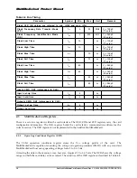
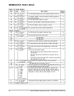
Table 4-19 Status Register
B i t s
T y p e
V a l u e
Description
C l e a r
C o n d .
3 1
E R
‘0’= no error
‘1’= error
The commands argument was out of allowed range for this card.
C
3 0
E R X
‘0’= no error
‘1’= error
A misaligned address, which did not match the block length was
used in the command.
C
2 9
E R
‘0’= no error
‘1’= error
The transferred block length is not valid.
C
2 8
E R
‘0’= no error
‘1’= error
An error in the sequence of erase commands occurred.
C
2 7
E X
‘0’= no error
‘1’= error
An invalid selection, sectors or groups, for erase.
C
2 6
E R X
‘0’= not protected
‘1’= protected
The command tried to write a write protected block.
C
2 5 - 2 4
Reserved
2 3
E R
‘0’= no error
‘1’= error
The CRC check of the previous command failed.
B
2 2
E R
‘0’= no error
‘1’= error
Command not legal for the current state
B
2 1
Not Applicable
2 0
Not Applicable
1 9
E R X
‘0’= no error
‘1’= error
A general or an unknown error occurred during the operation.
C
1 8
E X
‘0’= no error
‘1’= error
The card could not sustain data transfer in stream read mode
C
1 7
E X
‘0’= no error
‘1’= error
The card could not sustain data programming in stream write
mode
C
1 6
E R
‘0’= no error
‘1’= error
Can be one of the following errors:
- The CID register has been already written and can not be
overwritten.
- The read only section of the CSD does not match the card
content.
- An attempt to reverse the copy (set as original) or permanent
WP (unprotect) bits was made.
C
1 5
S X
‘0’= not protected
‘1’= protected
Only partial address space was erased due to existing WP
blocks.
C
1 4
Not applicable. This bit is always set to ‘0.’
1 3
S R
‘0’= cleared
‘1’= set
An erase sequence was cleared before executing because an out
of erase sequence command was received
C
1 2 - 9
S X
0 = idle
1 = ready
2 = ident
3 = stby
4 = tran
5 = data
6 = rcv
7 = prg
8 = dis
9-15 = reserved
The state of the card when the command was received. If the
command execution causes a state change, it will be visible to
the host in the response to the next command. The four bits are
interpreted as a binary coded number between 0 and 15.
B
8
S X
‘0’= not ready
‘1’= ready
Corresponds to buffer empty signaling on the bus. (RDY/BSY)
A
7 - 0
Reserved. Always set to ‘0.’

