18
Filters spare parts table
Model
Accessory filters and spare parts for CAD-COMPACT*
G4
M5
F7
F9
CAD COMPACT 500
AFR-CAD COMPACT 500 G4
AFR-CAD COMPACT 500 M5
AFR-CAD COMPACT 500 F7
AFR-CAD COMPACT 500 F9
CAD COMPACT 900
AFR-CAD COMPACT 900 G4
AFR-CAD COMPACT 900 M5
AFR-CAD COMPACT 900 F7
AFR-CAD COMPACT 900 F9
CAD COMPACT 1300 AFR-CAD COMPACT 1300 G4 AFR-CAD COMPACT 1300 M5 AFR-CAD COMPACT 1300 F7 AFR-CAD COMPACT 1300 F9
CAD COMPACT 1800 AFR-CAD COMPACT 1800 G4 AFR-CAD COMPACT 1800 M5 AFR-CAD COMPACT 1800 F7 AFR-CAD COMPACT 1800 F9
CAD COMPACT 2500 AFR-CAD COMPACT 2500 G4 AFR-CAD COMPACT 2500 M5 AFR-CAD COMPACT 2500 F7 AFR-CAD COMPACT 2500 F9
CAD COMPACT 3200 AFR-CAD COMPACT 3200 G4 AFR-CAD COMPACT 3200 M5 AFR-CAD COMPACT 3200 F7 AFR-CAD COMPACT 3200 F9
CAD COMPACT 4500 AFR-CAD COMPACT 4500 G4 AFR-CAD COMPACT 4500 M5 AFR-CAD COMPACT 4500 F7 AFR-CAD COMPACT 4500 F9
* In serial, the units are supplied with F7 as standard and M5 as extraction. All models allow the assembly of a second filter inside, obtaining, among others,
the following combinations: F7 + F9, M5 + F7 or G4 + F7.
7.2. ADDITIONAL FILTER INSTALLATION
The heat recovery is supplied with mounted filters.
Low pressure F7 filter for supply air and M5 for extract air.
Inside the heat recovery unit there is a specific rail for mounting a second additional filter (supplied as an accessory).
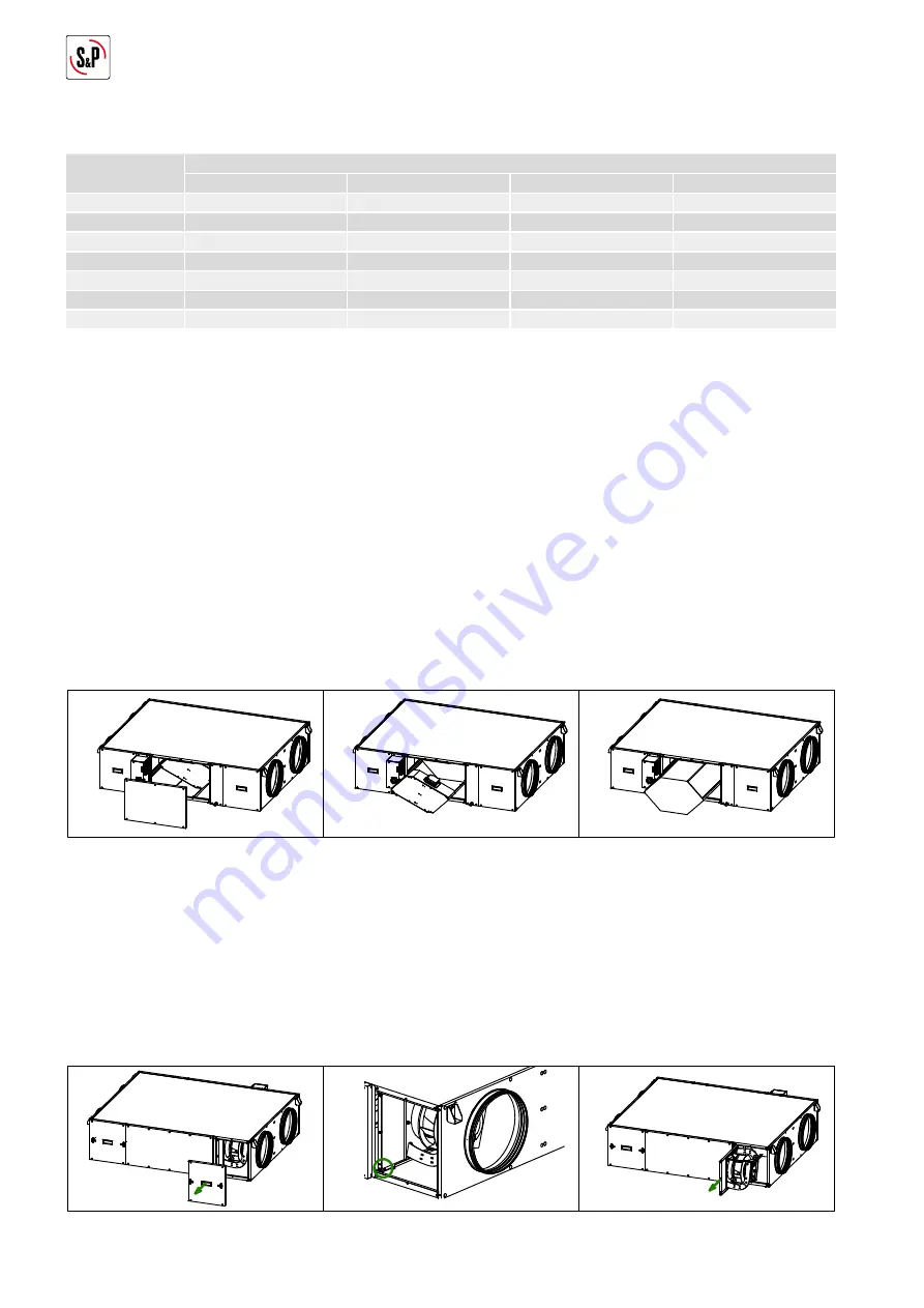
7.3. HEAT EXCHANGER
To perform the heat exchanger cleaning it is necessary to remove it from the unit. The disassembly can be easily done
from the lateral panel:
Core disassembly sequence per side
To disassemble of the heat exchanger follow the following sequence:
• Loosen the screws that hold the side panel. Before releasing the panel, ensure that it is well supported by the opera-
tor, preventing it from falling (Fig. 1).
• Remove the bypass assembly, releasing its electrical connector (Fig. 2).
• Pull the heat exchanger until it is completely removed from the equipment (Fig. 3).
Fig.1
Fig.3
Fig.2
7.4. FANS
It is not necessary to access the fan to carry out maintenance tasks, nor to carry out the electrical connection since both
fans are wired to the electrical cabinet. However, it is necessary to leave enough space around the equipment so that it
is possible to access the fans in the event of their failure. Do not install the heat exchanger against a wall or an obstacle
that prevents access to the fans.
In case of need to replace the fan, follow the following sequence:
• Remove the access panel for the affected fan (Fig. 1).
• Release the screws that lock the metal plate on which the fan is mounted (Fig. 2).
• Pull out the plate and once outside, remove the fan and proceed to replace it (Fig. 3).
Fig.1
Fig.2
Fig.3
Summary of Contents for CAD-COMPACT 500
Page 1: ...EN CAD COMPACT ECOWATT...


