

14
ENGLISH
HANGING (CEILING MOUNTED) AEROHEATERS
Carefully read the following instructions before using the
apparatus.
The EC N range of Aeroheaters comply with the European
safety regulations.
It is recommended that on receiving the apparatus it is
checked for defects and correct operation. Any defects
from origin are covered by the guarantee.
“In the framework of the implementation of Regulation
(EU) 2015/1188, implementing Directive 2009/125/EC
with regards to eco-design requirements for local space
heaters, it is required purchasing and installing of acces-
sory controller 5401652800 - CR-TEMP”
SAFETY RECOMMENDATIONS
• The installation should be carried out by a qualifi ed elec-
trician.
• All installation work should be carried out in accordance
with all applicable existing national and local regulations
covering electrical installations.
• Do not locate the cable in front of the air outlet nor in
contact with the walls of the Aeroheater during function.
• Do not place fl ammable objects within at least 50cm of
the hot air stream.
• Do not cover the Aeroheater with objects that may res-
trict the free fl ow of air. If the airfl ow is restricted this
may lead to overheating.
• Ensure that both the air inlet and outlet grilles are clean
and free from obstructions.
• Do not touch the apparatus with wet hands.
• If the apparatus is installed in a bathroom, it should be
installed in such a way that the switches or other con-
trols are not accessible to anyone bathing or having a
shower.
IMPORTANT SAFETY INFORMATION
• All S&P aeroheaters are certifi ed for insta-
llation in humid atmospheres.
• Before installation check that the mains
electrical voltage and frequency coincides
with the voltage shown on the product data
plate. The mains electricity supply should
be earthed. Do not use adapters or multiple
sockets.
• The appliance should be connected to the
mains electrical supply with correctly si-
zed cables and should include a double pole
switch with a contact clearance of at least
3 mm.
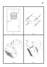
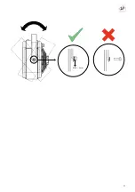
IMPORTANT
The apparatus should have suffi cient space around it for
the circulation of air (fi g.1).
The minimum distance between the Aeroheater and the
fl oor should be a minimum of 1.8m.
INSTALLATION
The minimum distances in fi g.1 should be observed.
The unit should be fi tted to a fi xed surface suitable for this
type of installation.
For installation the sequence below should be followed:
1. Using the support as a guide, mark the position of the
holes in the wall/ceiling and use the appropriate raw
plugs for the type of wall/ceiling. Fix the support using
screws (fi g.2).
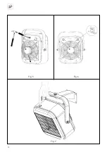
2. Hang and fi x the apparatus from the support (fi g.3).
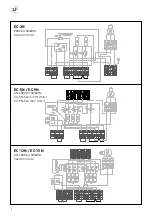
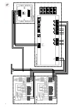
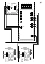
ELECTRICAL CONNECTION
All S&P Aeroheaters are designed for permanent connec-
tion to the electrical supply. When connecting to the mains
supply, follow the directives for low voltage installations
and the pertinent regulations for each country.
The installation should be provided with an isolator or dis-
connection device that disconnects all electricity supply to
the apparatus.
First, remove the upper cover (fi g.4). The electrical wi-
ring diagram is stored below this cover. Proceed with the
connection to the mains supply, having checked that the
mains supply voltage coincides with the voltage shown
on the product data plate. Use wiring conductors of the
same diameter and number shown on the diagrams that
correspond to each model. The connection to the mains
electrical supply should be made using protected cable
and should enter the apparatus through the cable grip
provided.
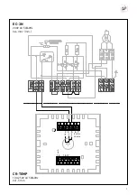
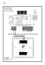
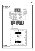
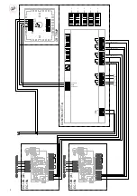
CONNECTION TO THE COMMUTATION SWITCH (CR-25)
These apparatus should be linked to the mains through a
commutation switch (CR-25), supplied separately.
To make the connection, use one of the previously mar-
ked holes, situated at the rear of the apparatus and fi t the
cable grip to the corresponding protected cable (fi g.5) For
electrical connections see the CR-25 commutation switch
diagram.
CONNECTION TO AN AMBIENT THERMOSTAT
(TR-1 or TR-2)
The ambient temperature can be regulated automatically
by connecting a thermostat to the apparatus.
ENGLISH
Summary of Contents for EC-3N
Page 1: ...EC 3N EC 5N EC 9N EC 12N EC 15N...
Page 9: ...9 Fig 1 Fig 3 Fig 2 Fig 4...
Page 10: ...10 Fig 5 Fig 7 Fig 6...
Page 11: ...11...
Page 38: ...38 Soler Palau Soler Palau...
Page 39: ......


