
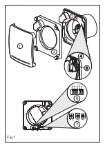
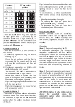

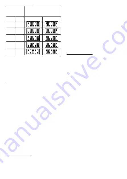
Constant
SW dip switch
position
The EcoAIR DESIGN may also operate
at high speed that is activated by an
external switch live or light switch (
S, T
and H versions
) or the humidistat built
(
H and M versions
) or the internal pull
cord switch (
M version
).
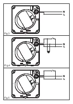
EcoAIR DESIGN S
The EcoAIR DESIGN S can operate in
two modes:
1. Continuous operation only on trickle
setting (Fig. 3).
Once the air volume set the fan is
connected to the mains and the unit
will operate continuously at this air
volume.
2. Continuous operation on trickle with
ability to boost at high speed.
The EcoAIR DESIGN is connected to
an external switch or light switch.
When the switch is closed, the fan
goes at full speed (not constant) until
the switch opens again (light off):
Fig.4- Wiring diagram to boost the fan
with the light switch.
Fig.5- Wiring diagram to boost the fan
with a separate switch
EcoAIR DESIGN T
This model is provided with an adjustable
over-run timer. The timer allows the fan
to continue to operate for the selected
period after the switch has been turned
off (fig.5).
Fig.4 shows how to connect the fan with
timer utilising the same switch as for the
lighting circuit to allow the fan to be
boosted.
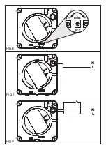
To set the timer, turn the potentiometer
“P2”
on the printed circuit board as (fig.
6).
- Manufacture setting:1 minute
- To reduce the "run on" time, turn
anticlockwise (min. 1 minute)
- To increase the "run on" time, turn
clockwise (max: 30 minutes).
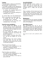
EcoAIR DESIGN H
Models provided with an electronic
humidistat which can be adjusted from
60% to 90 % RH (relative humidity) and
with a timer, adjustable between 1 and 30
minutes.
Operation
Case
1: Automatic operation (fig.7)
In automatic operation, the extractor
operates continuously at the setting
trickle speed. When the humidity level in
the room is higher than the set level the
fan is boosted to high speed. When the
humidity drops below the selected level
and after the selected period set on the
timer the fan automatically returns to
trickle.
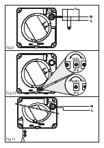
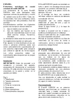
Case
2: Automatic operation as in case 1
with the facility to override the hygrostat
by means of an external switch (fig.8) or
the light switch (fig.9), when the humidity
level in the room is lower than the
selected level. In this case, the extractor
continues to operate for the selected
period set on the timer after the switch
light has been switched off.
ATENTION: When the humidity rate is
above
the
selected
value,
the
automatic option takes precedence
over the manual.
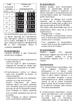
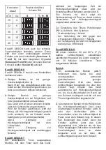
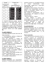
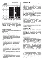
15
4
22
6
30
9
36
10
45
13
m
3
/h
l/s
S
T - H - M
volume
Summary of Contents for EcoAIR DESIGN
Page 1: ...EcoAIR DESIGN...
Page 2: ...Fig 1 6 7 P2 P3 P1 SW1 1 SW1 2 SW1 3 SW1 4 SW1 5 1 2 3 4 5...
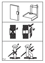
Page 3: ...Fig 2...
Page 4: ...Fig 4 Fig 3 Fig 5 L N L N L N...
Page 5: ...Fig 7 Fig 6 Fig 8 P2 min L N L N...
Page 6: ...Fig 10 Fig 9 Fig 11 L N P2 min P3 HR L N...
Page 31: ......
Page 32: ......
Page 33: ......
Page 34: ......
Page 41: ......
Page 42: ......
Page 43: ......


