Para aumentar el tiempo de tempo-riza-
ción girar en el sentido horario (max.: 30
minutos).
DECOR-100 CHZ "ECOWATT"
Modelos equipados con un higrostato elec-
trónico regulable entre el 60 y el 90% HR (%
Humedad Relativa) y con una temporización
ajustable entre 2 y 20 minutos.
Funcionamiento
Caso 1
o
c
it
á
m
o
t
u
a
o
t
n
e
i
m
a
n
o
i
c
n
u
f
n
E
:
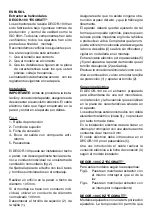
(fig.8) el aparato se pone en marcha auto-
máticamente cuando el nivel de humedad
en el local es superior al valor ajustado. Se
para cuando el nivel de húmeda vuelve por
debajo del valor ajustado y después del
tiempo fijado por el temporizador.
Caso 2: Funcionamiento automático con
posibilidad de puesta en marcha con el
interruptor de la luz (fig.6)
Funcionamiento automático similar al caso
1 y además con la posibilidad de poner el
aparato en marcha con el interruptor de la
luz cuando el nivel de humedad en el local
es inferior al valor ajustado. En este caso,
cuando se desconecta el interruptor (se
apaga la luz), el aparato sigue funcionando
el tiempo fijado por el temporizador.
ATENCIÓN: Cuando el nivel de humedad
relativa en el local sea superior al valor
el aparato siga funcionando el tiempo de-
terminado por la tempo-rización, después
que el interruptor haya sido desconectado
(fig.5).
El esquema fig.6 muestra como conectar
el aparato con temporización para que se
ponga en marcha con el mismo interruptor
que la luz.
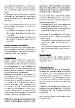
Para ajustar esta temporización, girar el
potenciómetro situado en el circuito im-
preso (fig.7):
- Para disminuir el tiempo de tempo-riza-
ción girar en el sentido anti-horario (min.:
1 minutos)
-
ajustado el funcionamiento automático
tiene prioridad sobre el funcionamiento
manual, es decir que no se podrá parar
el aparato con el interruptor.
El ajuste del valor de humedad se efectúa
por medio del potenciómetro “% Hr” que
se halla en el circuito impreso (fig.9) una vez
desmontada la rejilla (1):
- Para disminuir el nivel de humedad girar
en el sentido antihorario (min.: 60%)
- Para aumentar el nivel de humedad girar
en el sentido horario (max.: 90%).
Para ajustar la temporización, girar el po-
tenciómetro “t min.” situado en el circuito
impreso (fig.9):
- Para disminuir el tiempo de temporización
girar en el sentido antihorario (min.: 2
minutos)
- Para aumentar el tiempo de temporización
girar en el sentido horario (max.: 20 minu-
tos).
Mantenimiento
Sólo es necesaria una limpieza periódica
del extractor con un paño impregnado de
detergente suave.
Asistencia técnica
La extensa red de Servicios Oficiales S&P
garantiza una adecuada asistencia técnica
en cualquier punto de España. En caso de
observar alguna anomalía en el funciona-
miento del aparato rogamos presentarlo para
su revisión en cualquiera de los Servicios
mencionados donde será debidamente
atendido.
Cualquier manipulación efectuada en el
aparato por personas ajenas a los Servicios
Oficiales de S&P nos obligaría a cancelar
su garantía.
S&P se reserva el derecho de modificaciones
sin previo aviso.
ENGLISH
DECOR-100 “ECOWATT”
Axial Extractor Fans
The DECOR-100 extractor fan range is
manufactured to the high standards of
production and quality as laid down by the
international Quality Standard ISO 9001.
All components have been checked and
every one of the final products will have
been individually tested at the end of the
manufacturing process.
On reciept of the product we recommend
that you to check the following :
1- That it is the correct size.
2- That it is the correct model.
3- That the details on the rating label are
those you require: voltage, frequency
...
The installation must be carried out in
accordance with the electrical standards
in force in your country.
Installation
IMPORTANT: Before installing and wiring
the unit, ensure that the main supply is
disconnected.
Fig. 1:
1- Protection grille
2- Fixing screw
3- Connection terminals
4- Outlet with backdraught shutter
5- Cable entry
The DECOR-100 is suitable for wall or
ceiling mounting and can either discharge
directly to the outside or via an individual or
central ducting system (see Fig. 2).
The unit can be mounted on the wall or
ceiling using the 4 rubber blocks and the
screws provided.
Make a hole in the wall or ceiling of 105
mm dia.
If the unit is to be installed with individual
ducting, use a standard 100 mm dia.
duct.
Undo the two grille fixing screws (1).
Ensure that there are no obstructions to the
airflow and that the impeller turns freely.
Fix the extractor to the wall in such a way
that it is not distorted in order to avoid
noise generation or problems with the
rotation of the impeller. Make sure that the
backdraught shutter opens freely and has
not being damaged in transit. Introduce
the mains cable through the cable entry (5)
and fix it to the wall so that the fixing screw
(2) is above.
Connect the electrical wiring as set out below
and then mount the protection grille (1) and
tighten the screw (2).
Electrical connection
The DECOR-100 is an extractor desig-ned
for a single phase supply, with voltage and
frequency as indicated on the rating plate
of the unit. The units are manufactured with
double electrical insulation
(Class II) and therefore they do not need an
earth connection.
The electrical installation must include a
double pole switch with a contact clearance
of at least 3 mm.
The electrical cable must enter the DECOR-
100 through the cable entry (5).
Once the cable has been introduced proceed
using the electrical wiring diagram applicable
to the selected model.
DECOR-100 CZ “ECOWATT”
For these models use the following
diagrams:
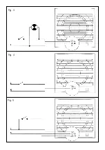
Fig.3: Switching the extractor through the
light switch.
Fig.4: To switch the fan through an
independent switch.
DECOR-100 CRZ “ECOWATT”
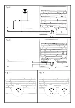
These models are provided with an adjustable
timer. The timer allows the fan to continue to
operate for the selected period after the
switch has been turned off (fig.5).
Fig.6 shows how to connect the fan with
timer utilising the same switch as for the
lighting.
To set the timer, turn the potentiometer on
the printed circuit board (fig. 7):
- To reduce the «run on» time, turn
Summary of Contents for ECOWATT DECOR-100
Page 2: ...Fig 1 Fig 2...
Page 3: ...Fig 3 Fig 4 Fig 5...
Page 4: ...Fig 6 Fig 8 Fig 7 Fig 9...
Page 30: ......
Page 31: ......
Page 32: ......
Page 33: ......
Page 34: ......
Page 35: ......


