background image

from 60 to 90 % RH ( % relative humidity).
They are fitted with a pullcord switch (IC)
enabling override of the fan when the relative
humidity level in the room is lower than the
set % RH value. A variable % RH rotary switch
on the front of the fan can be adjusted without
removing the grille.
Alternatively, the EDM-H, CH and VMH can
be powered by the light switch in preference
to the pull cord switch.

: Automatic operation ( Fig.9)

In this mode the pull cord switch is enclosed
behind the grille, in the "off" position (The pilot
lamp will not switch on).
The hygrostat causes the extractor to operate
automatically when the humidity level in the
room is higher than the level shown on the
variable rotary switch. Likewise, the extractor
will stop automatically when the humidity
level drops below the selected level.

: Automatic operation with pull cord

override facility (Fig. 10).
Automatic operation as in case 1 with the
facility to override the hygrostat by means of
the pull cord when the humidity level in the
room is lower than the selected level on the
rotary switchl. When the pull cord is used to
power the fan the red pilot lamp (L) turns on.

: Automatic operation with facility to

override by light switch ( Fig. 11)
The operation of the extractor is the same as
in case 2 although, the EDM is connected to
the light switch (IL) instead of the pull cord.
In this case leave the pullcord inside the fan in
the "off" position .

This model is equipped with a photoelectric
cell that activates the extractor when the light
intensity is greater than 30 Lux. Therefore, to
avoid the fan working continuously, these
models must be installed only in rooms with
poor illumination. As an indication, an

intensity of 30 Lux is to low to allow normal
reading ( Fig. 12).

Models fitted with pullcord switch
EDM-100 M and VM : Fig. 13.
EDM-100 VMH see the explanation for
models H,CH and VMH.
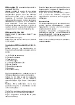
(Fig. 14)
These models have been designed for
installation on window (single or double
glazing) or wall.

1 and 10 : Protection grille

6 : Outlet

2 : Cable entry

7 : Rubber joints

3 : Connection cover

8 : Spacers

4 : Fixing screw

9 : Threaded ring

5 : Connection terminals

For the installation, make a hole of 105 mm
diameter in the glazing or on the wall.
Loosen the screws on the front and back
protection grilles (1 and 10). Loosen the
threaded ring (9) and remove the 4 spacers
(8).
Mount the EDM depending on the installation
requirements so the glass or the wall is
between the two rubber joints (7):

Fig. 5a : All the spacers on the outside
Fig. 5b : All the spacers on the inside
Fig. 5c : Spacers both on the outside and the
inside

When the unit is installed in double glazing or
on a wall, it is possible that all the spacers are
not needed.
Once the above operations are finished, fix
the EDM with the threaded ring, make the
electrical connection and mount again the
protection grilles.

The extractor needs only a periodical
cleaning using a cloth lightly impregnated
with a soft detergent.

We recommend you not to try to dismantle or
remove any other parts than those mentioned
as any tampering would automatically cancel
the S&P guarantee. If you detect any fault,
contact your S&P dealer.

Operation

Case 1

WARNING: When the extractor is
operating by hygrostat, the red pilot lamp
on the grille of the EDM is not on.

Case 2

Case 3

WARNING: When the relative humidity
level in the room is higher than the level
selected on the rotary switch, the
automatic operation overrides the manual
operations (i.e.pull cord or light switch),
that is, the extractor cannot be stopped by
either the pull cord or the light switch.

Maintenance

After Sales Service

EDM model EC

EDM models M,VM and VMH

EDM models VM and VMH. Installation

S&P reserves the right to alter specifications
without notice

Summary of Contents for EDM-100 Series

Page 1: ...taje Instruction leaflet Notice de montage Montageanweisungen Montage en gebruiksaanwijzing Instru es de montagem Istruzioni per l installazione Anv ndar instruktion Brugervejledning Instrukcja obslug...

Page 2: ...Fig 1 Fig 2 Fig 3 Fig 4...

Page 3: ...Fig 6 Fig 5 Fig 7...

Page 4: ...Fig 9 Fig 8 Fig 10...

Page 5: ...Fig 12 Fig 11 Fig 13...

Page 6: ...Fig 14 Fig 15...

Page 7: ...abajo fig 4 Una vez conectado como se indica a continuaci n volver a montar la rejilla de protecci n 1 y apretar el tornillo 4 El EDM es un extractor preparado para alimentarse de una red monof sica...

Page 8: ...para ser instalados en cristal simple o doble o tabique 1 10 Rejillas de protecci n 2 Pasacables 6 Soporte 3 Tapa conexi n 7 Junta de goma 4 Tornillo de sujeci n 8 Separadores 5 Ficha conexi n 9 Anil...

Page 9: ...ical wiring as explained hereafter and then mount the protection grille and fixed it by tightening the screw 4 The EDM is an extractor designed for a single phase supply with voltage and frequency as...

Page 10: ...h pullcord switch EDM 100 M and VM Fig 13 EDM 100 VMH see the explanation for models H CH and VMH Fig 14 These models have been designed for installation on window single or double glazing or wall 1 a...

Page 11: ...cher la rotation de l h lice et rendre l appareil bruyant ou inop rant Raccorder le c ble lectrique comme indiqu ci apr s replacer la grille de protection et serrer la vis de fixation 4 L EDM est un...

Page 12: ...sibilite de mise en marche manuelle avec l interrupteur de la lumi re fig 12 Fonctionnement similaire au cas 2 o l interrupteur cordelette est remplac par l interrupteur commandant la lumi re dans la...

Page 13: ...5c S parateurs r partis de part et d autre de la vitre Si la vitre ou cloison est paisse il se peut que tous les l ments s parateurs ne soient pas n cessaires Pour finir fixer l EDM avec la bague de...

Page 14: ...es gepr ft werden Es ist darauf zu achten da das Geh use des L fters bei der Montage nicht eingeklemmt wird um die Leichtg ngigkeit des Laufrades nicht zu beeintr chtigen und st rende Ger usche zu ver...

Page 15: ...Automatikbetrieb Abb 9 Der Ein Aus Zugschalter IC befindet sich in der Stellung Aus Betriebskontrollampe L leuchtet nicht Der Zugschalter liegt hinter dem Schutzgitter Das Ger t wird ber den Hygrosta...

Page 16: ...anzringe 8 entfernen Zum Einbau des L fters eine der Gummidichtungen an der Innenseite und die andere an der Au enseite des Fensters der Wand anbringen Abb 5a Alle Distanzringe au en Abb 5b Alle Dista...

Page 17: ...elektrische kabel moet worden ingevoerd in de EDM ofwel via de kabeligang 7 als de kabel ingewerkt is ofwel via de kabelingang 2 als de kabel zichtbaar blijft In het laatste geval moet de kabel worde...

Page 18: ...atorlampje L wel aan bij het inschakelen van de afzuigventilator Automatische werking met de mogelijkheid in te schakelen met de verlichtingsschakelaar fig 11 De werking is gelijkaardig aan die van ge...

Page 19: ...rs nodig Schroef vervolgens de ring met draad op de EDMvoordebevestiging Sluithetapparaataan enplaatsbeidebeschermingsroostersterug Het is enkel nodig om regelmatig de afzuigventilator met een met zac...

Page 20: ...pelo isolante 2 se a instala o for com cabo vista neste caso o cabo deve ser introduzido conforme se mostra na fig 3 Fixe o aparelho parede de maneira que o parafuso de sujei o 4 esteja abaixo fig 4...

Page 21: ...luz piloto L acende funcionamento autom tico com possibilidade de funcionamento com o interruptor de luz fig 11 Funcionamento similar ao caso 2 onde o interruptor com corrente substitu do pelo interr...

Page 22: ...eciso utilizar todos os separadores uma vez feito isto sujeite o EDM com o anel roscado ligue o aparelho e volte a montar as grelhas de protec o Basta uma limpeza peri dica do extractor com um pano hu...

Page 23: ...acciato dato che in questo caso potrebbe essere ostacolata la rotazione della ventola con i conseguenti rumori Eseguire l allacciamento elettrico secondo le istruzioni che seguono a continuazione coll...

Page 24: ...uperiore al valore impostato con la manopola Quando il livello d umidit di nuovo inferiore al valore impostato l apparecchio si ferma automaticamente Funzionamento automatico con la possibilit di mett...

Page 25: ...nella parete Svitare le viti della griglia di protezione anteriore e posteriore 1 e 10 Svitare il raccordo filettato 9 e ritirare i 4 separatori 8 Montare l EDM collocando tra le due guarnizioni di g...

Page 26: ...kopplad enligt som f ljer s tt tillbaka skyddsgallret 1 och skruva fast skruven 4 EDM r en fl kt som r gjord f r enfasn t med sp nning och frekvens som indikerat p fl ktens m rkskylt Fl ktarna r utrus...

Page 27: ...VMH Fig 14 Dessa modeller r designade f r att installeras p f nster enkelt eller dubbelt glas eller p v gg 1 och 10 Skyddsgaller 2 Kabeling ng 3 Kopplingslock 4 F stskruv 5 Kabelanslutning F r instal...

Page 28: ...dning i s tilf lde skal ledningen indf res som vist p fig 3 Fastg r apparatet p v ggen s ledes at fastholdelsesskruen 4 vender nedad fig 4 Efter at have udf rt forbindelsen som angivet monteres beskyt...

Page 29: ...gtighedsniveauet kommer ned under den valgte v rdi Automatisk funktion med mulighed for manuel start med stop start knappen fig 10 Automatisk funktion der ligner mulighed 1 og ligeledes med mulighed f...

Page 30: ...efter fastg res EDM ventilatoren med skrue ringen apparatet forbindes elektrisk og beskyttelses gitterne p s ttes Periodevis reng ring af ventilatoren med klud v det i mild s be er tilstr kkelig Det o...

Page 31: ...nie zamontowac kratka ochronna dokrecajac ja sruba mocujaca 4 Wentylatory EDM sa przeznaczone do zasilania pradem zmiennym jednofazowym napiecie i czestotliwosc jak na tabliczce znamionowej Posiadaja...

Page 32: ...wlaczenie wentylatora po przekroczeniu w pomieszczeniu poziomu wilgotnosci ustawionego pokretlem Wentylator wylacza sie automatycznie po spadku wilgotnosciponizejustawionegopoziomu Praca automatyczna...

Page 33: ...ybowym u ycie wszystkich modu w nie jest konieczne Zlo one elementy nale y skr ci przy pomocy pier cienia mocuj cego 9 przeprowadzi pod czenie elektryczne i zamontowa kratki ochronne 1 i 10 P r z e d...

Page 34: ...4 z stal dole obr 4 Elektrick kabel se do EDM prot hne bu otvorem 7 je li veden zd nebo vstupem kabelu 2 vede li po povrchu V tomto p pad se kabel prot hne tak jak je zn zorn no na obr 3 Kryt zapojen...

Page 35: ...pad se p i zapnut ventil toru rozsv t sv teln kontrolka L automatick chod s mo nost zapnout spot ebi s ov m vyp na em osv tlen m stnosti ve kter je ventil tor EDM nainstalov n obr 11 Jedn se o chod ja...

Page 36: ...se zp t ochrann m ky Ventil tor je nutn pravideln ot rat had kem namo en m v jemn m istic m prost edku Jak koliv z sah do spot ebi e jinou osobou ne pracovn kem autorizovan opravny je d vodem ke zru...

Page 37: ...EDM 100 EDM ISO 9001 1 2 3 4 EDM 2 105 100 4 1 EDM 6 7 2 3 4 4 1 4 E D M II 3 3 4 5 13 5 6 T CT R CR EC 7 1 DM S C EDM T CT R CR EC...

Page 38: ...e 8 CW CCW H CH VMH 60 90 RH IC H CH VMH 9 IC L 10 1 IC L 11 2 IL EDM IC L T CT 1 EDM 2 3 R CR EC EDM C CT EC CR CH M EDM H CH VMH...

Page 39: ...EDM EDM M VM VMH C VMH 1 10 30 30 12 EDM 100M VM 13 EDM 100 VMH H CH VMH EDM M VM 14 2 3 4 5 6 7 8 9 105 1 10 9 4 8 EDM 7 15a 15b 15c EDM S P S P S P...

Page 40: ...a l piviennist 2 tai puhaltimen takana olevasta l piviennist 7 Jos johto kiinnitet n sivusta tulee se tehd l piviennin 2 sen kautta Asennna johto l piviennin l pi 3 ja kytke kiinni kytkent rimaan 5 As...

Page 41: ...vetonarulla kun kosteus on matalampi kun asetusarvo Kun puhallin k y vetonarulla merkkivalo palaa Asento 3 Automaattinen k ytt k ynnistys katkaisijalta fig 11 Toiminta sama kun asento 2 paitsi ett EDM...

Page 42: ...osia kuin n iss ohjeissa mainittuja avata k sitell lainkaan Yll mainitsemattomien osien k sitteleminen peruuttaa automaattisesti takuun voimassaolon Jos puhaltimessa huomataan vikoja tai muita ongelmi...

Page 43: ...EDM 100 100 S P 100 98 1 2 3 4 5 6 7...

Page 44: ...2 100 105 100 4 100 3 6b 6a...

Page 45: ...7 8 9 10 11 EDM 100S EDM 100C 7 100 EDM 100R EDM 100E EDM 100EC EDM 100 CR 30 12 EDM 100 EDM 100EC EDM 100 EDM 100EC EDM 100R EDM...

Page 46: ...30 30 S P S P...

Page 47: ......

Page 48: ...Soler Palau Sistemas de Ventilaci n S L U C Llevant 4 08150 Parets del Vall s Barcelona ESPA A Tel 93 571 93 00 Fax 93 571 93 01 Fax int 34 93 571 93 11 e mail consultas solerpalau com Web www solerp...

Reviews: