background image

12

EN

ELECTRICAL CONNECTION

This appliance is considered to be suitable for use in countries having a 
warm damp equable climate as specifi ed in IEC 60721-2-1. It may also 
be used in other countries.

The EDM is an extractor designed for a single phase supply, with voltage and fre-
quency as indicated on the rating plate of the unit. The units are made with double 
electrical insulation (Class II) and therefore they do not need an earth connection.
The electrical installation must include a double pole switch with a contact clea-
rance of at least 3 mm.
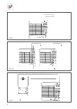
The electrical cable must be introduced to the EDM through the slot (7) if the wire 
is within the wall, or through the cable entry (2) if the installation is with a surface 
mounted cable; in this case, the cable must be introduced as shown on Fig. 3b 
and not as shown on Fig. 3a.
Once the cable has been introduced, fix it with the flange (3) and proceed to the 
appropriate electrical wiring depending on the EDM model.

EDM models S and C

For these models use the following diagrams:
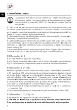
Fig. 4: Switching the extractor through the light switch.
Fig. 5: To switch the fan through an independent switch.

EDM models T, CT and CR

Models fitted with fixed (aprox. 9 minutes) not adjustable timer (T and CT) or 
adjustable (CR). The timer enables the extractor to continue running during the 
time delay, after the switch has been switched off (Fig. 6). The diagram on Fig. 7 
shows how to connect a unit fitted with timer using the light switch.
Model CR has an adjustable timer. To adjust the timer, turn the rotary switch on 
the Printed Circuit Board (Fig. 8a):
• To decrease the time delay turn it Counter Clockwise (CCW).
• To increase the time delay turn it Clockwise (CW).

EDM models C, CT, CR, and CH

These models are fitted with automatic shutter.

WARNING: The opening of the shutter is facilited by means of a thermal system 
that needs some seconds to open completely.

EDM models H and CH

Models H and CH are provided with an electronic hygrostat which can be adjusted 
from 60 to 90% RH (% relative humidity). They are fitted with a pullcord switch 

Summary of Contents for EDM-200 Series

Page 1: ...EDM 200 ES SV EN PL FR IT CS AR DE NL PT...

Page 2: ......

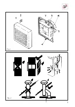
Page 3: ...3 Fig 1 Fig 2...

Page 4: ...4 Fig 3 Fig 4 Fig 5...

Page 5: ...5 Fig 8a Fig 8a Fig 6 Fig 7 n nL...

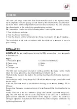
Page 6: ...6 Fig 9 Fig 10 Fig 11...

Page 7: ...n 5 Ficha de conexi n 6 Boca de salida 7 Muesca El EDM puede ser instalado en techo o pared con descarga directa hacia el ex terior a conducto individual o a un sistema de ventilaci n comunitario g 2...

Page 8: ...xi n el ctrica a la cha de conexi n 5 seg n el modelo de EDM EDM modelos S y C Para estos modelos seguir los esquemas Fig 4 Puesta en marcha del extractor con el mismo interruptor que el de la luz Fig...

Page 9: ...l extractor funciona autom ticamente gracias al higros tato la luz piloto roja situada en la reja del EDM no se ilumina Caso 2 Funcionamiento autom tico con posibilidad de puesta en marcha ma nual con...

Page 10: ...tencia t cnica en cualquier punto de Espa a En caso de observar alguna anomal a en el funcionamiento del aparato rogamos presentarlo para su revisi n en cual quiera de los Servicios mencionados donde...

Page 11: ...rille 2 Cable entry 3 Flange 4 Fixing screw 5 Connection terminals 6 Outlet 7 Slot The EDM can be installed on wall or ceiling and the discharge can be made direct to the outside or to a ducting indiv...

Page 12: ...trical wiring depending on the EDM model EDM models S and C For these models use the following diagrams Fig 4 Switching the extractor through the light switch Fig 5 To switch the fan through an indepe...

Page 13: ...of the EDM is not on Case 2 Auyomatic operation with pull cord override facility Fig 10 Automatic operation as in case 1 with the facility to override the hygrostat by means of the pull cord when the...

Page 14: ...ergent AFTER SALES SERVICE We rocommend you not to dismantle or remove any other parts than those men tioned as any tampering would automatically cancel the S P guarantee If you detect any fault conta...

Page 15: ...ch ma g 1 1 Grille de protection 2 Passe c bles lat ral 3 Serre c ble 4 Vis de xation de la grille 5 Bornier 6 Bouche de sortie 7 Passe c ble arri re L EDM peut tre install soit au mur soit au plafond...

Page 16: ...version de l EDM EDM versions S et C Pour ces mod les sont propes s deux sch mas Fig 4 Le m me interrupteur commande la lumi re dans la pi ce et la mise en route de l EDM Fig 5 Un interrupteur ind pen...

Page 17: ...rieur la valeur indiqu e par le bouton molet ATTENTION Quand l extracteur fonctionne automatiquement par l interm diaire de l hygrostat le t moin lumineux rouge situ sur la face avant de l EDM reste e...

Page 18: ...ttoyer l appareil ni s occuper de son entre tien sans surveillance ENTRETIEN Nettoyer r guli rement la grille 1 pour viter l accumulation de pussi re Nous vous conseillons de ne pas d monter d autres...

Page 19: ...e 6 Ausblasstutzen 7 Hintere Kabeldurchf hrung Der L fter kann sowohl an der Decke oder der Wand installiert werden wobei die Abluft direkt nach au en geblasen wird als auch an einem einzelnen Schacht...

Page 20: ...Fall ist die hintere Kabeldurchf hrung 7 zu ffnen und das Kabel durchzuf hren im zweiten Fall ist das Kabel gem Abb 3b durch die seitliche Kabeldurchf hrung 2 zu f hren Nach Einf hrung des Kabels ist...

Page 21: ...BETRIEBSARTEN 1 Automatikbetrieb Abb 9 Der Ein Aus Zugschalter IC be ndet sich in der Stellung Aus Betriebskon trollampe L leuchtet nicht Der Zugschalter liegt hinter dem Schutzgitter Das Ger t wird...

Page 22: ...Lichtschalter ausgeschaltet werden bis der vorgegebene Feuchtegrad wieder erreicht ist BEDIENUNGSANLEITUNG DiesesGer tdarfnurnacheinerentsprechenden Unterweisung bereinesichereHandhabungvon Kindern be...

Page 23: ...ing De EDM kan tegen de wand of het plafond geplaatst worden met uitblaas re chtstreeks naar buiten via een afzonderlijk kanaal of via een gemeenschappelijk ventilatiesysteem g 2 Boor een gat in de wa...

Page 24: ...afhankelijt is van het EDM model EDM modellen S en C Voor deze modellen de volgente schema s volgen Fig 4 Aanzetten van de ventilator met dezelfde schakelaar als die van het licht Fig 5 Een afzonderl...

Page 25: ...neer de ventilator dankzij de hygrostaat automatisch werkt is het rode controlelampje op het rooster van de EDM uit Geval 2 Automatische werking met mogelijkheid tot handbediening via de aan uit treks...

Page 26: ...schoongemaakt met een doek gedrenkt in een mild reinigingsmiddel TECHNISCHE ONDERSTEUNING S P waarborgt een doeltreffende technische ondersteuning Mocht u een afwij king in de werking opmerken dan vr...

Page 27: ...4 Parafuso de aperto 5 Ficha de liga o 6 Boca de sa da 7 Entrada para o cabo O EDM pode ser instalado no tecto ou na parede com descarga directa para o exterior para conduta individual ou para um sis...

Page 28: ...o el ctrica segundo cada modelo EDM EDM modelos S e C Para estes modelos seguir os esquemas Fig 4 Ligar o aparelho com o mesmo interruptor da luz Fig 5 Um interruptor independente para ligar o aparel...

Page 29: ...ATEN O Quando o exaustor funciona utom ticamente gra as ao higrostato a luz piloto encarnada situada na grelha do EDM n o se acende Caso 2 Funcionamento autom tico com possibilidade de se ligar manual...

Page 30: ...Poder o recorrer ao seu fornecedor pelo que em caso de qualquer anomalia no funcionamento do aparelho dever o envi lo para ser revisto Qualquer manipula o efectuada no aparelho por pessoas estranhas...

Page 31: ...s Figur 1 1 Front skyddsgaller 2 Kabelgenomf ring 3 Kabelavlastare 4 Skruv 5 Kopplingsplint 6 Utlopp 7 Kabelgenomf ring EDM ktarna kan installeras b de i tak och v gg Fl kten kan anslutas till en egen...

Page 32: ...den dras enligt g 3b och ej enligt 3a Drag sedan kabeln genom kabelavlastningen 3 och koppla in kabeln p ko pplingsplinten 5 enligt nedan beroende p modell EDM modell S och C Anv nd f ljande kopplings...

Page 33: ...gheten r l gre i rummet n det inst llda v rdet VARNING N r kten r inkopplad med hj lp av hygrostaten t nds ej kontro llampan p kten Alternativ 2 Automatisk drift med m jlighet till tv ngsstyrning med...

Page 34: ...h llsfri Fl kten skall endast periodvis torkas av utv ndigt med en fuktad trasa SERVICE Vi rekommenderar att du ej monterar is r n gra andra delar n de n mnda i denna instruction Eventuell p verkan av...

Page 35: ...cjami prawnymi obowi zuj cymi w Polsce UWAGA Wentylatory EDM nie s przeznaczone do monta u w kuchennych sys temach wentylacyjnych INSTALACJA UWAGA Przed rozpocz ciem monta u wentylatora od cz zasilani...

Page 36: ...m ze byc doprowadzony do wentylatora d tylu 7 jezeli przewo dy sa w murze lub z boku 2 jezeli przewody s a prowadzone po powierzchni ciany W przypadku bocznego doprowadzenia nale y kabel zains talowa...

Page 37: ...ylator wy cza si automa tycznie po spadku wilgotno ci ponizej ustawionego poziomu UWAGA Podczas pracy wentylatora uruchamianego przez hydrostat czerwona lampka kontrolna jest wy aczon Spos b 2 Praca a...

Page 38: ...nych nale y od czy zasilanie od wentilatora Wentylatory wymagaj tylko okresowego czyszczenia przy u yciu ciereczki i de likatnego detergentu Monta wentylatora w spos b niezgodny z instrukcj oraz praca...

Page 39: ...5 Terminale d allacciamento 6 Bocca d uscita 7 Incavo L EDM pu essere installato sul sof tto o la parete con scarico diretto dell aria all aperto ad un condotto individuale o ad un sistema centrale d...

Page 40: ...le o superiore a 3 mm L installazione si pu realizzare con il cavo sottotraccia forando l incavo poste riore previsto a tale scopo oppure con il cavo a vista introducendolo attraverso il passacavo lat...

Page 41: ...sare l interruttore tipo cordina FUNZIONAMENTO Caso 1 Funzionamento automatico g 9 L interruttore ON OFF tipo cordina IC in posizione OFF spia luminosa spenta La cordina deve trovarsi nell interno del...

Page 42: ...apparecchio I bambini non devono giocare con l apparecchio Il prodotto pu essere pulito perio dicamente utilizzando un panno umido MANUTENZIONE C unicamente bisogno provvedera a una pulizia regolare d...

Page 43: ...pev ovac roub 5 p ipojovac svorky 6 v stupn hrdlo 7 kabelov prostup EDM 200 je vhodn pro mont na st nu nebo strop a m e b t instalov n s v stupem p mo p es st nu nebo do potrubn ho syst mu samostatn h...

Page 44: ...pomoc kabelov p chytky 3 a zapojte dle od pov daj c ho sch matu v z vislosti na typu EDM EDM typy S C Pro tyto typy pou ijte n sleduj c sch mata Obr 4 Ovl d n ventil toru spole n se sv tlem Obr 5 Ovl...

Page 45: ...esne pod zvolenou rove POZOR Je li ventil tor uveden do provozu pomoc hygrostatu erven kont rolka na m ce EDM nesv t P pad 2 Automatick provoz ventil toru s ovl d n m pomoc tahov ho vyp na e obr 10 Au...

Page 46: ...bez dozoru DR BA Ventil tor vy aduje jen pravideln i t n vlhk m hadrem a slab m ist c m pro st edkem TECHNICK SERVIS Zjist te li u spot ebi e jakoukoli provozn z vadu obra te se na autorizovan techni...

Page 47: ...47 AR...

Page 48: ...48 AR D IEC 60721 2 1...

Page 49: ...49 AR DQG...

Page 50: ...50 AR 8...

Page 51: ......

Page 52: ...S P SISTEMAS DE VENTILACI N S L U C Llevant 4 Pol gono Industrial Llevant 08150 Parets del Vall s Barcelona Espa a Tel 34 93 571 93 00 www solerpalau com Ref 9023010101...

Reviews: