


ENGLISH
Thank you for placing your confidence in S&P by buying
this product. It has been manufactured following current
technical safety regulations in accordance with EC
standards. Please read this instruction booklet carefully
before installing and starting up the product. It contains
important information on personal and user safety
measures to be followed while installing, using and
carrying out maintenance work on the equipment. Once
the product has been installed, please hand in this
booklet to the end user. Check that the appliance is in
perfect condition while unpacking. Any fault or damage
caused in origin is covered by the S&P guarantee.
Ensure that all the values of main supply are compatible
with those indicated on the rating plate.
Transport and manipulation.
- The packaging used for this appliance has been
designed to withstand normal transport conditions.
The appliance must always be transported in its
original packaging as not doing so could deform or
damage the product.
- The product should be stored in a dry place in its
original packaging, protected from dust and dirt until it
is installed in its final location. Do not accept delivery if
the apparatus is not in its original packaging or shows
clear signs of having been manipulated in any way.
- Do not place heavy weight on the packed products
and avoid knocking or dropping it.
- When manipulating heavy products, adequate
elevating machinery should be used to avoid harming
people or damaging to the product itself.
Safety on Installation:
- Before handling this appliance, make sure that it is
disconnected from the power supply.
- Installation must only be carried out by a qualified
professional.
- The installation must be in accordance with the
electrical standards and regulations in force in your
country.
- The electrical installation must include a double pole
switch with a contact clearance of at least 3 mm,
correctly sized and in accordance with the electrical
standards of the country of installation.
- This appliance is not intended for use by young
children or infirm persons unless they have been
adequately supervised by a responsible person to
ensure that they can use the appliance safely. Young
children should be supervised to ensure that they do
not play with the appliance.
- Once it has been commissioned, the appliance must
comply with the following Directives:
Low Voltage Directive 2006/95/CE
Electromagnetic
Compatibility Directive
2004/108/EC.
- The installer must use heating batteries that are in
perfect condition
- When you install the battery, make sure that all
mounting parts are in place and that the structure on
which they are installed is resistant enough to support
the battery.
- The electrical heaters are designed for indoor
installation. The maximum air temperature at the
outlet must not be over than 40ºC
- Fit the battery respecting the airflow direction
indicated by the arrow located on the battery.
- Use the batteries only for heating clean air. If the
heating elements become dirty, there is a risk of fire.
We recommend installing an air filter upstream from
the heater with a minimum distance of twice diameter
between the filter and the heater.
- Do not use these batteries in explosive or corrosive
atmospheres.
- The maximum air ambient temperature around the
heater must be lower than 35ºC
- Do not install the battery in a place of the duct system
where there is a risk of condensation.
- The electrical connection should provide a device for
controlling the air flow. The heating battery has to be
operative only when it reaches the minimum flow or
an air velocity higher than 1.5 m/s.
- The electrical installation has to ensure that the
electric heater battery cannot start up if the fan is
switched off. The battery has to start up after or at the
same time as the fan.
- The electrical installation has to ensure that the fan
cannot be stopped when the electric battery is
operating. The fan has to stop after the battery has
been switched off and cooled.
- Never fit MBE-R batteries with the terminal box
downwards.
- The distance between the battery and components of
the duct system such as bends, dampers or other
types of accessories must be at least twice the
diameter of the MBE-R type battery.
- In the event of insulating the heating battery use only
non-flammable insulation (M0) and place it keeping
the rating plate visible and the connection box cover
easily accessible.
- The distance between the sheet metal casing of the
battery and inflammable materials must be more than
150mm. If these distances cannot be maintained,
provide insulation around the battery.
- If the batteries are fitted to the terminal part of the
installation, a grille or other type of protection must be
fitted to prevent any direct contact with the heater
battery.
- Please follow the connection diagrams for the
electrical connection.
Starting up
Before starting up the appliance, make sure that:
- The appliance is well secured and the electrical
connections have been carried out correctly.
- The electrical safety devices are duly connected
- There are no loose materials or fitting remains in the
area of the heater battery.
- The earth fitting are adequately connected.
- Electrical safety devices are correctly connected, duly
adjusted and ready to use.
- The wire and electrical connections inputs are
correctly sealed and water-tight.
When starting up the apparatus:
- During the operating period the heater battery must
never be touched.
- If any electrical devices blow, the apparatus must be
quickly disconnected from main supply. The whole
installation should be carefully checked before trying
to start up the apparatus again.
- Check electricity consumption
Maintenance.
- Before manipulating the heater battery, make sure
that it is disconnected from the main supply. Prevent
the possibility of anyone else connecting it while it is
being manipulated.
- The apparatus must be regularly inspected. These
inspections should be carried out bearing in mind the
machine’s working conditions, in order to avoid dirt or
dust accumulating.
- All maintenance and repair work should be carried out
in strict compliance with each country’s current sa
fety
regulations.
Recycling.
EEC Standards, together with the responsibility we
should assume with future generations in mind, oblige us
to recycle all the materials we can. Therefore please
deposit all left-over material and packaging in their
corresponding recycling containers and hand in the
replaced machines to the nearest handler of this type of
waste product.
If you have any queries about S&P products, please
contact our After-Sales Service Network if you are in
Spain or your local S&P dealer in any other country. If in
doubt, please visit our Web-page
www.solerpalau.com
MBE-R electric heating battery
Technical data:
The electric batteries MBE-R comply with EC Standards
The electric batteries MBE-R incorporate 2 thermal
protectors fitted as standard: one for automatic reset at
60ºC and another one at 120 ºC with manual reset.
Supply voltage:
Single-phase: 1/230V AC, 50Hz
Three-phase: 2/400V or 3/400V AC, 50Hz
Protection rating: IP43
Maximum outlet temperature: 40ºC
Maximum ambient temperature: 35ºC
Minimum air velocity: 1.5 m/s
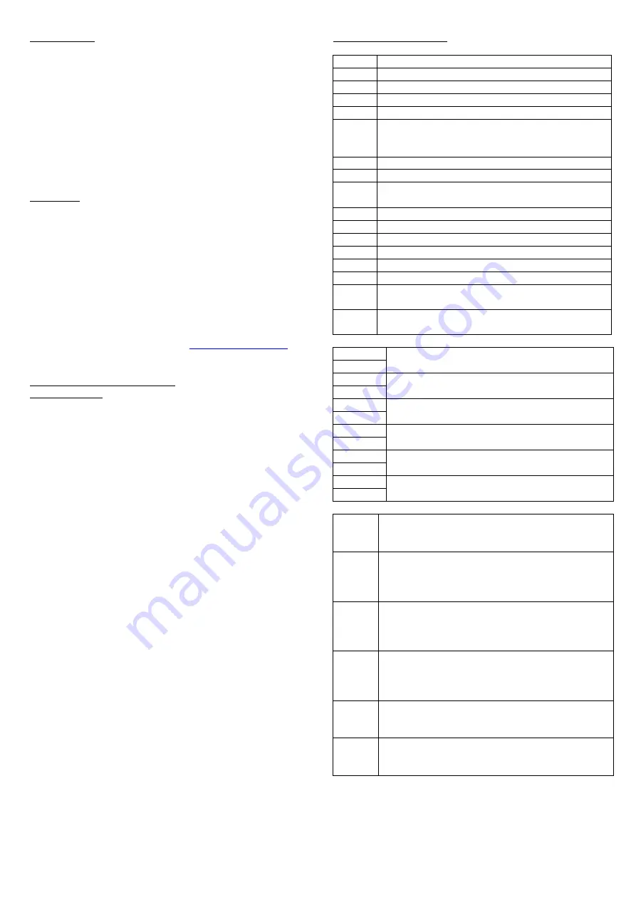
Index for wiring diagram
REF
DESCRIPTION
1
General ON/OFF switch (heater and fan)
2
Post-ventilation timer
3
Heater relay
4
Fan relay
5
The electrical installation must include a
double pole switch with a contact clearance of
at least 3mm
6
Safety overheat automatic thermostat
7
Safety overheat manual reset thermostat
8
Jumper to select internal or external
temperature setting
8a
Internal temperature setting
–
with jumper
8b
External temperature setting
–
without jumper
9
LED
10
Maximum temperature setting
11
Minimum temperature setting
12
Air volume controller
–
pressure switch
13
External temperature controller with output 0-
10V
14
External temperature set-point with output 0-
10V
PCB-1
Main temperature sensor connection
PCB-2
PCB-3
External temperature set point connection
PCB-4
PCB-5
Not used
PCB-6
PCB-7
Limit temperature sensor connection
PCB-8
PCB-9
External temperature controller connection
with output 0-10V
PCB-10
PCB-11
Pressure switch connection. If not, put a
bridge.
PCB-12
FIG.A
Supply air temperature control with sensor
TGK 330 in duct and temperature set point
adjusted with heater potentiometer
FIG.B
Supply air temperature control with sensor
TGK 330 in duct and temperature set point
adjusted with external potentiometer type TBI
30
FIG.C
Room temperature control with sensor TGR
530, temperature set point adjusted with
heater potentiometer and supply air limitation
with TGK 330 sensor in duct
FIG.D
Room temperature control with sensor TGR
430, temperature set point adjusted with
sensor potentiometer and supply air limitation
with TGK 330 sensor in duct
FIG.E
External heating control with output 0-10V.
Heating power varies from 0 to 100% when
output varies from 2V to 9,5V.
FIG.F
Extension of the wiring diagrams Fig. A and C,
using an external temperature set point with
output 0-10V.
Summary of Contents for MBE-R
Page 1: ...MBE R...
Page 2: ...MBE R 90 45 0 45 0...


