41
M2
M1
21
5
20
63
62
13
6
48
49
53
54
6
7
8
M+P-26A-2071
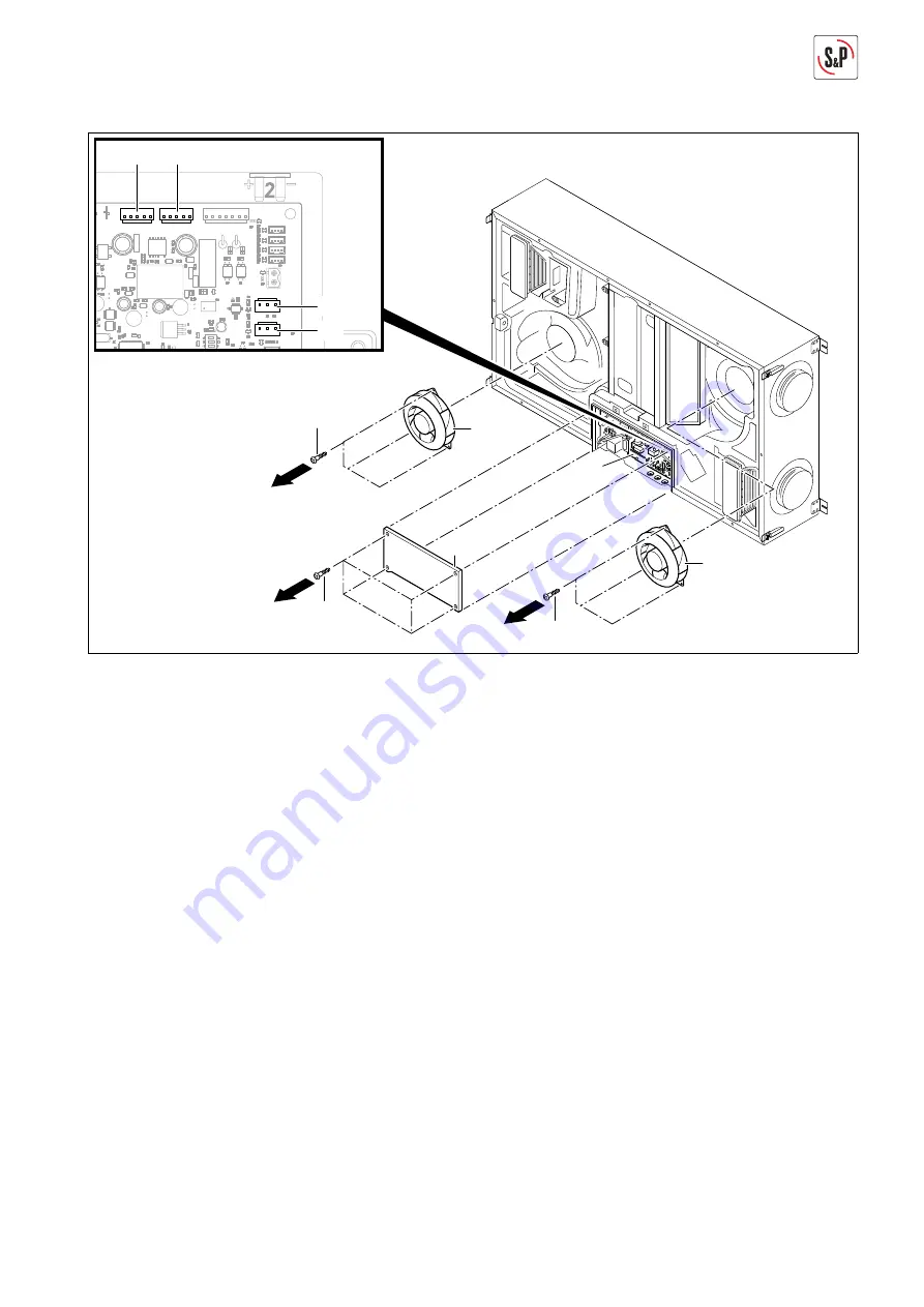
7. Remove screws Torx 10 (20) and take off cover (21)
(Arrow 6).
8. Disconnect voltage supply M1 (48) and M2 (49), as well
as control signals M1 (53) and M2 (54) on the main cir-
cuit board.
9. Remove screws Torx 30 (62) and replace extract air fan
(6) (Arrow 7).
10. Remove screws Torx 30 (63) and replace supply air
fan (13) (Arrow 8).
11. The installation takes place in the reverse sequence.
12. Reconnect condensate line, see page 12.
Summary of Contents for NEMBUS 210
Page 1: ...NEMBUS 210 EN...
Page 2: ......


