background image

11



In case of direct connection to the mains, the installer has a connection card inside of 

connection box. 


2.2.- Fastening the hood  




The hood must be centred with respect to the cooking surface, at a minimum height of 650 

mm. 




Use screws and plugs, but first make sure that they are correct for the type of wall where the 

hood is to be fitted. 




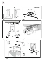
Before setting Operations, remove the filter panels 

(Fig.4). 




Drill 6 holes A-B-C of 

Φ

 6, shown in 

(Fig.3). 




Insert plugs and screws 

(Fig.3-A) 

without tightening completely, in such a manner that the 

hood can be supported from them. 

Then attach the Hood body to the wall using two internal screws. 

(Fig.3-C). 




Fix the decorative telescopic support 

(Fig.5-1

). Make sure all screws are tight.


Extract version


  Using a joining pipe of diameter 150mm, connect output ring

 (Fig.5-2-A) 

and the discharge 

opening. Secure the connection joints, to avoid air leaks, with self adhesive tape. 


  If installation is thought with a duct of diameter 120mm, you can install 150 to 120mm duct 

reducer.     


  At the time of joining the hood with extraction duct, double-checked that back draft shutter 

is opening and closing correctly.   


Filter version




If your installation does not have a discharge opening to the outside, you will have to ask your 

supplier for 

active circular carbon filters

, which are supplied as an accessory and are not 

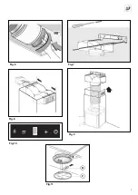
included as standard equipment. For mount them, see (

Fig.6

). 




Fix in the wall the plastic bracket just below the decorative telescopic support 

(Fig.7). 

The two pins of the support position have to fit with the holes of the plastic derivation. 




You can easily cut the plastic shunt to fit well inside the top of the telescopic cover and the air 

outlets are properly aligned with the exhaust grill. 

(Fig.8).




Using a joining pipe of diameter 150 mm, connect output ring and the plastic shunt. 

Secure the connection joints to avoid the air leaks, with self adhesive tape. 

(Fig.9).


2.3.- Fitting the decorative telescopic cover


  Fix the lower part of the decorative telescopic cover with hood body using inner screws 

(Fig.5-2-B).


  Extend the top of the decorative telescopic cover and secure it to the upper support with 

the two supplied screws. 

(Fig.5-1A)

Summary of Contents for VA Series

Page 1: ...VA 900 BLACK...

Page 2: ...2 Fig 1 Fig 2 Fig 4 Fig 3 Fig 5 6 1 B 230 235 245 C 300 300 A B A...

Page 3: ...3 Fig 6 Fig 8 Fig 9 Fig 11 Fig 7 Fig 10...

Page 4: ...donde circule aire que sea utilizado para evacuar humos de aparatos alimentados con energ a no el ctrica Cuando funcionen simult neamente la campana de aspiraci n y un quemador de gas horno chimenea...

Page 5: ...no debe de ser utilizado por personas incluidos ni os con disfunciones f sicas sensoriales o mentales o con inadecuada experiencia y conocimiento si no es bajo supervisi n de una persona responsable...

Page 6: ...es de fijaci n extraer el filtro anti grasa Fig 4 Respetando las medidas realice los 6 agujeros A B C de 6 indicados en la Fig 3 Inserte los tornillos Fig 3 A sin apretar del todo y cuelgue la campana...

Page 7: ...podr seleccionar hasta 4 velocidades de funcionamiento En la pantalla se indica la velocidad seleccionada Velocidad 1 LENTA Velocidad 2 MEDIA Velocidad 3 R PIDA Velocidad 4 TURBO temporizada Pulsando...

Page 8: ...n del carb n activo depende del uso m s o menos prolongado de la campana del tipo de cocina y de la frecuencia con la cual se limpia el panel filtrante exterior Limpie frecuentemente todos los restos...

Page 9: ...ed by non electric energy If the hood and a burner boiler stove oven etc are in operation simultaneously in the same room and the correct combustion of the latter appliances depends on ambient air for...

Page 10: ...e carrying out any maintenance or cleaning operations always disconnect the hood from the mains When replacing bulbs always use bulbs of the same type and power never more powerful If the cleaning ope...

Page 11: ...20mm duct reducer At the time of joining the hood with extraction duct double checked that back draft shutter is opening and closing correctly Filter version If your installation does not have a disch...

Page 12: ...ppears The hood will start up in speed 1 LOW for 10 minutes Then it will remain stopped for 50 minutes showing a letter C on the screen This cycle 10 minutes ON 50 minutes OFF will continue indefinite...

Page 13: ...move the bulb in the direction indicated by the arrow and change it for one of the same kind and characteristics MAX 20W G4 12V ATTENTION Do not touch the bulb after long period of the device operatin...

Page 14: ...e d air neuf ext rieur dans la pi ce est correctement dimensionn e pour assurer une bonne combustion Cette entr e d air neuf ne doit pas pouvoir tre obstru e Pour les vacuations vers l ext rieur respe...

Page 15: ...E CES AVERTISSEMENTS 2 INSTALLATION L installation et le raccordement lectrique doivent tre effectu s par une personne qualifi e 2 1 Raccordement lectrique La hotte est double isolation lectrique et n...

Page 16: ...ment sur le support permettent le montage correct de la d rivation en plastique Il est possible de recouper la d rivation en plastique pour qu elle s adapte bien l int rieur de la partie sup rieure de...

Page 17: ...a hotte d pend de la r gularit avec laquelle s effectue l entretien surtout des filtres graisses et du filtre charbon actif Les filtres m talliques servent retenir les particules de graisse en suspens...

Page 18: ...tures g n rations nous obligent recycler le mat riel nous vous prions de ne pas oublier de d poser tous les l ments restants de l emballage dans les containers correspondants de recyclage et d emmener...

Page 19: ...a n o el ctrica Quando funcionem simultaneamente a campanula de aspira o e um quemador de g s forno chamin etc que dependam do ar do ambiente e que sejam alimentados com energ a n o el ctrica recomend...

Page 20: ...vel adequadamente instru da para a utiliza o do aparelho As crian as devem ser supervisionadas para assegurar de que n o brincam com o aparelho Antes de realizar qualquer opera o de manuten o ou limpe...

Page 21: ...ao exterior Assegure a conex o de junte los para evitar fugas de ar mediante fita adhesiva Se na instala o esta pr vida de um tubo de 120mm pode ser utilizado o redutor de 150 a 120mm No momento de ac...

Page 22: ...a funcionar durante 10 minutos Passado ese tempo a camp nula desliga se autom ticamente Modo renova o de ar Com a camp nula desligada e presionado a tecla durante 2 segundos podemos seleccionar este m...

Page 23: ...las Fig 11 extraia com precau o o anel de cristal mediante um desaparafusador Atire o mesmo lustre e substitua a por umas do mesmo tipo e caracter sticas MAX 20W G4 12V ATEN O N o toque os lustres ap...

Page 24: ...S P SISTEMAS DE VENTILACI N S L U C Llevant 4 Pol gono Industrial Llevant 08150 Parets del Vall s Barcelona Espa a Tel 34 93 571 93 00 Fax 34 93 571 93 01 www solerpalau com Ref 1441272...

Reviews: