29
EN
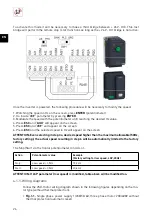
•
Fig.3.4.
Three phase power supply 3/400/50-60, three phase motor 230/400V o 400V with
thermal protection.
•
Fig.2.3.
Single phase power supply 1/230/50-60, three phase motor 230/400V with ther-
mal protection.
•
Fig.2.4.
Three phase power supply 3/400/50-60, three phase motor 230/400V o 400V with
thermal protection.
IMPORTANT:
In case of activating the thermal protection, it will be necessary to make
the corresponding electrical connection by wiring the motor’s TP to the corresponding
terminals of the drive. It will also be important to verify that switch SW2 is in LI6 position.
5.5. ENABLE PTC THERMAL PROTECTION
For those motors that incorporate a PTC type protection probe, the VFTM320 drives have a dedi-
cated control mode.
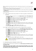
The fi rst step will be to verify that the SW2 micro switch is positioned to the right (PTC.
Next,
proceed to unlock the equipment (5.1 paragraph) and then follow the steps below:
• Fan stopped and
“rdY
” displayed in the screen
(no b24V – DI3 and +24V – DI1).
• Press
ENTER
and turn wheel on clock wise direction until
“COnF-”
appears in the screen.
• Press
ENTER
and turn wheel on clock wise until “
FULL
” appears.
• Press
ENTER
and turn wheel on clock wise until “
FLt-
” appears.
• Press
ENTER
and turn wheel on clock wise until “
PtC-
” appears.
• Press
ENTER
and turn wheel on clock wise until “
PtCL
” appears.
• Press
ENTER
on desired function knowing that:
−
“no”
: Disabled
−
“A5”
: Always. The PTC probe performs uninterrupted supervision even if the power supply is
not connected (as long as the control remains connected to the power supply).
−
“rd5”
: With potentiometer. The probe performs supervision while the power supply to the drive
is connected.
−
“r5”
: Motor running. Supervision when the motor is connected.
• Press
ESC
successively until
“rdY”
appears in the screen.
5.5.1. Wiring diagram
Carry out VSD-motor connection scheme indicated in the following fi gures depending on the
motor type used with thermal protector:
•
Fig.1.3.
Single phase power supply 1/230/50-60, three phase motor 230/400V with PTC
thermal protection.
•
Fig.1.4.
Three phase power supply 3/400/50-60, three phase motor 230/400V o 400V with
PTC thermal protection.
5.6. ON/OFF CONTROL BY EXTERNAL SWITCH
This function is available in all the working modes described in this manual. By using an external
switch (potential free signal) it is possible to perform a remote stop / start actuation.
For this, and depending on the programming mode used, it will be necessary to carry out the corre-
sponding wiring diagram, replacing the existing bridge with a wiring to the external switch.
5.6.1. Wiring diagrams
•
Manual control with frontal wheel/potentiometer mode:
on/off external switch located
between te24 – DI3.


