ENGLISH
16 / 40
NT_51895501_AKOR ST HR-AN_140325.docx
3.3 Installation
Ventilation unit
3.3.1
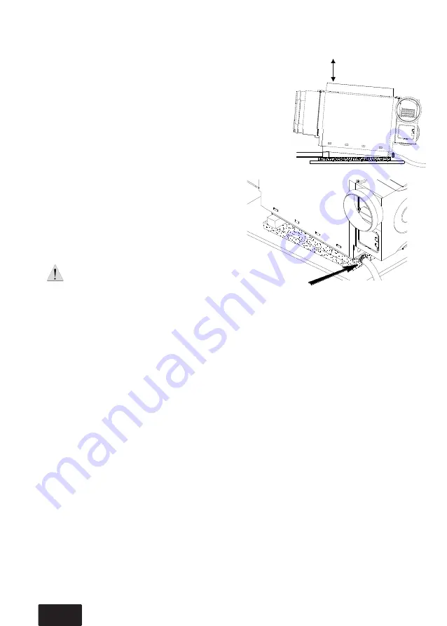
The unit is designed to be installed in a suitable
cupbaord or in the attic. The unit must be
installed horizontally and then at a slope of
about 5º (slope height 30 mm) so that
condensation can drain through the drain
placed on the side of the unit (see diagram
opposite).
It is advisable to place the unit on a piece of
foam or glass wool to prevent noise
transmission.
Do not forget to connect the drain to a 19 mm
internal diameter pipe connected to the waste
water network: install the pipe with a regular
slope, without any high points, to facilitate the
flow of condensate and insulate the pipe to
prevent frost.
Use a clamp to adjust the hose to the drain.
Ensure a clearance of 450 mm above the group
in order to remove the heat exchanger during
maintenance operations.
Extraction and air output system
3.3.2
The network is made of insulated PVC flexible duct and must be as simple as possible:
Avoid unnecessary lengths and bends
Use large radius bends
The duct should never be crushed
The extraction network consists of Ø125 mm duct for the kitchen and Ø80 other damp areas.
The exhaust of the extraction group is connected to a roof output by a Ø150 duct.
The fresh air output network is built using a Ø150/Ø125/Ø125 distribution unit (not supplied) and two
4-nozzle Ø80 splitters (supplied)
The fresh air output is made from Ø150 duct.
slope 30 mm
(tilt 5°)
Free space: 450 mm


