hdf3asl7sm-rev1218
sandpiperpump
.
com
Model HDF3-A/HDF4-A
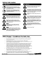
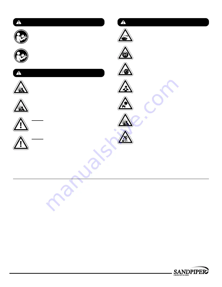
IMPORTANT
Read the safety warnings and instructions in this manual
before pump installation and start-up. Failure to comply with
the recommendations stated in this manual could damage the
pump and void factory warranty.
When used for toxic or aggressive fluids, the pump should
always be flushed clean prior to disassembly.
Airborne particles and loud noise hazards. Wear eye and ear
protection.
Before maintenance or repair, shut off the compressed air line,
bleed the pressure, and disconnect the air line from the pump.
Be certain that approved eye protection and protective clothing
are worn at all times. Failure to follow these recommendations
may result in serious injury or death.
When the pump is used for materials that tend to settle out
or solidify, the pump should be flushed after each use to
prevent damage. In freezing temperatures the pump should be
completely drained between uses.
Before pump operation, inspect all fasteners for loosening
caused by gasket creep. Retighten loose fasteners to prevent
leakage. Follow recommended torques stated in this manual.
CAUTION
WARNING
Nonmetallic pumps and plastic components are not UV
stabilized. Ultraviolet radiation can damage these parts and
negatively affect material properties. Do not expose to UV light
for extended periods of time.
In the event of diaphragm rupture, pumped material may enter
the air end of the pump, and be discharged into the atmosphere.
If pumping a product that is hazardous or toxic, the air exhaust
must be piped to an appropriate area for safe containment.
This pump is pressurized internally with air pressure
during operation. Make certain that all fasteners and piping
connections are in good condition and are reinstalled properly
during reassembly.
Take action to prevent static sparking. Fire or explosion can
result, especially when handling flammable liquids. The pump,
piping, valves, containers and other miscellaneous equipment
must be properly grounded.
Safety Information
ATEX Pumps - Conditions For Safe Use
WARNING
Pump not designed, tested or certified to be powered by
compressed natural gas. Powering the pump with natural
gas will void the warranty.
Use safe practices when lifting
kg
WARNING
The use of non-OEM replacement parts will void (or negate)
agency certifications, including CE, ATEX, CSA, 3A and EC1935
compliance (Food Contact Materials). Warren Rupp, Inc. cannot
ensure nor warrant non-OEM parts to meet the stringent
requirements of the certifying agencies.
1.
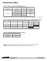
Ambient temperature range is as specifi ed in tables 1 to 3 on the next page
(per Annex I of DEKRA 18ATEX0094X)
2.
ATEX compliant pumps are suitable for use in explosive atmospheres when the equipment is properly grounded in
accordance with local electrical codes
3.
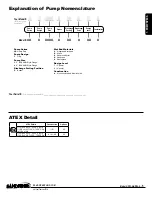
Non-Metallic ATEX Pumps only — See Explanation of Pump Nomenclature / ATEX Details Page
Conductive Polypropylene, conductive Acetal or conductive PVDF pumps are not to be installed in applications where the
pumps may be subjected to oil, greases and hydraulic liquids.
4.
The optionally provided solenoids shall be protected by a fuse corresponding to its rated current (max 3*Irat according
to EN 60127) or by a motor protecting switch with short circuit and thermal instantaneous tripping (set to the rated
current) as short circuit protection. For solenoids with a very low rated current, a fuse with the lowest current value
according to the indicated standard will be suffi cient. The fuse may be accommodated in the associated supply unit
or shall be separately arranged. The rated voltage of the fuse shall be equal or greater than the stated rated voltage of the
solenoid. The breaking capacity of the fuse shall be as high as or higher than the maximum expected short circuit current
at the location of the installation (usually 1500 A). The maximum permissible ripple is 20% for all dc solenoids.
*Not applicable for all pump models — See Explanation of Pump Nomenclature / ATEX Details Page
5.
When operating pumps equipped with non-conductive diaphragms that exceed the maximum permissible projected area,
as defi ned in EN ISO 80079-36 : 2016 section 6.7.5 table 8, the following protection methods must be applied
- Equipment is always used to transfer electrically conductive fl uids or
- Explosive environment is prevented from entering the internal portions of the pump, i.e. dry running.
6.
Pumps provided with the pulse output kit and used in the potentially explosive atmosphere caused by the presence of
the combustible dust shall be installed in such a way that the pulse output kit is protected against impact
*Not applicable for all pump models — See Explanation of Pump Nomenclature / ATEX Details Page
UNIVERSAL ALL AODD


