


S&S Northern Ltd. Wallace Francis House, Barnes Wallis Way, Buckshaw Village, Lancashire, PR7 7JN T. 01257 470983 www.snsnorthern.com
J. WIRING FOR AT-RU1 RELAY UNIT DIN RAIL MOUNTABLE
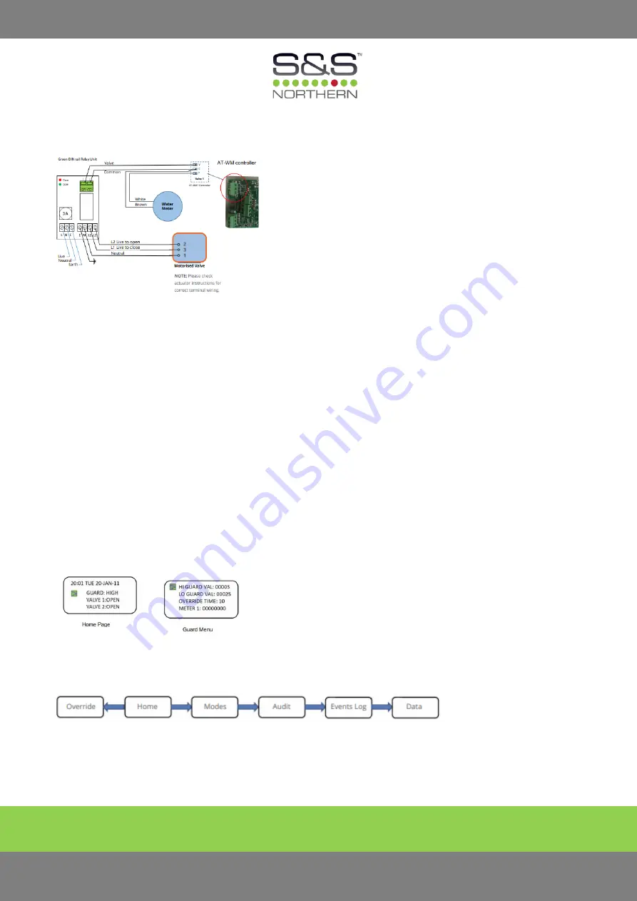
AT-RU1 CONNECTIONS
Power Connections to Relay (Mains), 230Vac supply L = Live, N = Neutral, E = Earth
Power Connections to Relay (Relay Valve), 230Vac supply L1= Live Close, L2= Live Open, N = Neutral, E = Earth
Control Connections from AT-WM Controller 1= V (Valve) 2=C (Common)
NOTE: Wiring should only be done by a qualified electrician
NOTE: These diagrams are shown for one water meter and one solenoid valve. If two are required, the second set should
be wired to the “Valve 2” terminals.
Diagrams shown are for one water meter/solenoid valve. When two are required, use Valve 2 terminals for the second
set.
K. OPERATING THE AT-WM FOR DAY TO DAY USE.
Push any key to wake the display which will show the Home Page, see below. The home page shows the time, date, the
level of guard and the state of the valves.
Use the keys (Up, Down, Left & Right) to navigate. Use OK button to switch between High & Low Guard Levels. Use OK to
open and close valves. To return to Home, press (Left) at any time.
To change a numerical value press OK to select the line; (Up, Down) to change the value and OK to confirm changes. Use
the (Up, Down, Left & Right) to navigate the menu.


