KBox C-103-NGSF - User Guide, Rev. Proof of Concept
www.kontron.com
// 63
9.4.
Cleaning the Air Filter
The air filter is inserted in the holder (Figure 22, pos. 2) at the bottom side of the
fan tray slot (Figure 22, pos. 6). The soiling of the air filter (Figure 22, pos. 3) is
caused by the pollution of the operating environment. A heavily soiled air filter can
cause excessive heating of the device. For this reason we recommend to clean the air
filter as often as necessary. The air filter can be changed during operation of the
system.
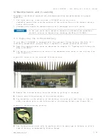
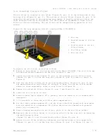
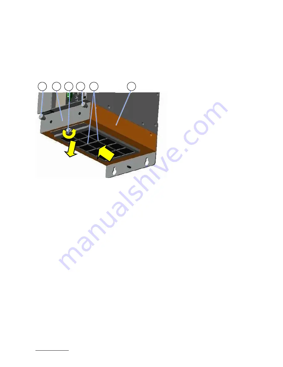
Figure 35: Fan tray extension (detail: shown as KBox C-103-NGSF-1)
To replace the air filter, proceed as follows:
1.
Ensure to have access to the bottom side of the KBox C-103-NGSF. The air filter may
be replaced without removing the fan tray (Figure 35, pos. 1).
2.
Loosen the knurled screw (Figure 35, pos. 3) that secures the air filter holder
(Figure 35, pos. 4) to the fan tray slot (Figure 35, pos. 5); refer to step 1 in
Figure 35.
3.
Pull the air filter holder out of the positioning holes, (Figure 36, pos. 9) into
the marked direction (see Figure 35) and pull it down. Put the air filter holder
aside for later reassembly; refer to step 2 and 3 in Figure 35.
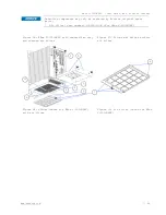
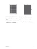
4.
Remove the soiled air filter (Figure 35, pos. 3 and Figure 36, pos. 6).
5.
Clean the air filter as follows:
6.
Rinse in water (up to approx. 40°C; possibly with the addition of a standard mild
detergent).
7.
It is possible to clean the air filter with compressed air.
8.
For dirt that contains grease/oil, the air filter should be rinsed with warm water
with the addition of a degreaser. Air filter should not be cleaned with powerful
water jets or wrung out.
9.
After cleaning and drying the air filter, place it in the air filter holder.
10.
Reattach the air filter holder to the bottom side of the fan tray slot by inserting
the positioning latches
(Figure 36, pos. 8) into the positioning holes (Figure 36, pos. 9).
11.
Secure the air filter holder by tightening the knurled screw to the tapped hole
(Figure 36, pos. 4) of the fan tray slot (Figure 35, pos. 5 or Figure 36, pos. 3).
1
Fan tray
2
Knurled screws of the fan
tray
3
Knurled screw of the air
filter holder
4
Air filter holder
5
Fan tray slot
3
2
1
4
5
3
1
2
2


