background image

FlatView – User Guide, Rev. 2.0 


www.kontron.com 


// 9 


Table of Contents 


Symbols ................................................................................................................................................................................................................. 6


For Your Safety .................................................................................................................................................................................................... 7


High Voltage Safety Instructions .................................................................................................................................................................. 7


Special Handling and Unpacking Instruction ............................................................................................................................................ 7


Lithium Battery Precautions .......................................................................................................................................................................... 8


General Instructions on Usage...................................................................................................................................................................... 8


Quality and Environmental Management ................................................................................................................................................. 8


Disposal and Recycling .................................................................................................................................................................................... 8


WEEE Compliance.............................................................................................................................................................................................. 8


Table of Contents ............................................................................................................................................................................................... 9


List of Tables ....................................................................................................................................................................................................... 11


List of Figures ..................................................................................................................................................................................................... 11


1/


Introduction .......................................................................................................................................................................................... 12


2/


General Safety Instructions for Equipment ............................................................................................................................... 13


 Electromagnetic Compatibility EU ....................................................................................................................................................... 15


2.1.

 Electrostatic Discharge (ESD) .............................................................................................................................................................. 15


2.2.
2.2.1. Grounding Methods .............................................................................................................................................................................. 15


3/


Scope of Delivery ................................................................................................................................................................................ 16


 Accessories ................................................................................................................................................................................................. 16


3.1.
3.1.1. Type Label and Product Identification ............................................................................................................................................. 17


4/


Product Description ........................................................................................................................................................................... 18


 Product Views ............................................................................................................................................................................................ 18


4.1.

5/


Technical Data .................................................................................................................................................................................... 20


 Technical Specification ........................................................................................................................................................................... 20


5.1.

 Environmental Specification ................................................................................................................................................................ 24


5.2.

 Directives and Standards ...................................................................................................................................................................... 25


5.3.

6/


Order Information.............................................................................................................................................................................. 26


7/


Mechanical Specification ................................................................................................................................................................ 27


 10.1“ Mechanical Dimensions ................................................................................................................................................................ 27


7.1.
7.1.1. 10.1“Monitor Built-in ............................................................................................................................................................................. 27


 10.4“Mechanical Dimensions ............................................................................................................................................................... 28


7.2.
7.2.1. 10.4” Monitor Built-in ........................................................................................................................................................................... 28


7.2.2. 10.4“ Monitor VESA .............................................................................................................................................................................. 29


 12.1“ Mechanical Dimensions ............................................................................................................................................................... 30


7.3.
7.3.1. 12.1“ Monitor Built-in  (SVGA ,XGA) .................................................................................................................................................. 30


7.3.2. 12.1“ Monitor VESA (SVGA, XGA) ....................................................................................................................................................... 30


7.3.3. 12.1” Monitor Built-in (WXGA) ............................................................................................................................................................ 31


7.3.4. 12.1“ Monitor VESA (WXGA) ............................................................................................................................................................... 32


 15.0“Mechanical Dimensions ............................................................................................................................................................... 33


7.4.
7.4.1. 15.0” Monitor Built-in ........................................................................................................................................................................... 33


7.4.2. 15.0“ Monitor VESA............................................................................................................................................................................... 34


 15.6“ Mechanical Dimensions ............................................................................................................................................................... 35


7.5.
7.5.1. 15.6” Monitor Built-in (slim) ............................................................................................................................................................... 35


7.5.2. 15.6” Monitor VESA (slim) .................................................................................................................................................................. 36


7.5.3. 15.6” Built-in Variant ............................................................................................................................................................................ 37


Summary of Contents for kontron FlatView Series

Page 1: ...USER GUIDE www kontron com 1 FlatView Doc User Guide Rev 2 0 Doc ID 1061 6343...

Page 2: ...FlatView User Guide Rev 2 0 www kontron com 2 This page has been intentionally left blank...

Page 3: ...e suitable for the specified use without further testing or modification Kontron expressly informs the user that this user guide only contains a general description of processes and instructions which...

Page 4: ...at your risk To minimize the risks associated with your products and applications you should provide adequate design and operating safeguards You are solely responsible for compliance with all legal...

Page 5: ...declares regional General Terms Conditions of Sale and Purchase Order Terms Conditions Visit http www kontron com terms and conditions For contact information refer to the corporate offices contact in...

Page 6: ...ibed by the law may endanger your life health and or result in damage to your material ESD Sensitive Device This symbol and title inform that the electronic boards and their components are sensitive t...

Page 7: ...int shall remain connected The earth ground cable shall be the last cable to be disconnected or the first cable to be connected when performing installation or removal procedures on this product Speci...

Page 8: ...ct then re pack it in the same manner as it was delivered Special care is necessary when handling or unpacking the product See Special Handling and Unpacking Instruction Quality and Environmental Mana...

Page 9: ...Product Identification 17 4 Product Description 18 Product Views 18 4 1 5 Technical Data 20 Technical Specification 20 5 1 Environmental Specification 24 5 2 Directives and Standards 25 5 3 6 Order In...

Page 10: ...t in 47 7 10 2 23 8 Monitor VESA 47 8 Installation and Start 48 Mounting Instructions Built in 48 8 1 Startup Procedure 49 8 2 8 2 1 Connecting to a Power Supply 49 9 Connectors 50 Input Power Connect...

Page 11: ...t Power Connector Pinout 50 Table 10 DVI Connector Pinout 51 Table 11 DP Connector Pinout 51 Table 12 USB Port Pinout 51 Table 13 LED Power Indicator s Color Description 52 Table 14 List of Acronyms 6...

Page 12: ...lti touch access to real time actionable data making it the perfect fit for SCADA Supervisory Control and Data Acquisition and Manufacturing Execution Systems MES process visualization and other contr...

Page 13: ...ion The DC power supply should be able to be switched off and switched on via an isolating switch The unit is only completely disconnected from the DC main power supply when the DC power cable is disc...

Page 14: ...A reliable protective earth connection is provided A suitable easily accessible disconnecting device is used in the application e g overcurrent protective device if the product cannot be disconnected...

Page 15: ...tions to prevent damage Always take the following precautions ESD Sensitive Device Keep electrostatic sensitive parts in their containers until they arrive at the ESD safe workplace Always be properly...

Page 16: ...or mating 1 EE04 100001 01 Phoenix Power Subcon w housing mating connector Power Cable EU 1 840 0059 EU Power cable length 1 8m AC DC Power Supply 24 VDC Kit 1 ER40 100001 01 Power supply 24 VDC and P...

Page 17: ...lyester matt silver label located on the rear side of the FlatView Figure 2 Type Label 1 Module name 2 Module number 3 Part number 4 Barcode part number 5 Serial number 6 Barcode serial number 7 Elect...

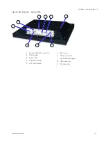
Page 18: ...View 1 TFT Display with resistive touch 2 Front plate Figure 4 Rear Side View Monitor Built in 1 Display Port connector 2 OSD keypad 3 Power LED 4 LAN option only 5 LPC option only 6 Rear cover 7 Mou...

Page 19: ...on com 19 Figure 5 Rear Side View Monitor VESA 1 Display Port DP connector 2 OSD keypad 3 Power LED 4 LAN option only 5 LPC option only 6 Rear cover 7 Power connector Insert Power Supply 8 USB connect...

Page 20: ...kg 3 9 kg 4 7 kg 4 7 kg 4 7 kg Protection glass option option option option option PCAP Multitouch option option option option option Resistive touch On request option option option On request Color R...

Page 21: ...5 kg Protection glass option option option option PCAP Multitouch option option option option Resistive touch option option option option Color RAL 7021 black anthracite Fastening VESA 75 75 or 100 1...

Page 22: ...kg 8 4 kg Protection glass option option option option PCAP Multitouch option option option option Resistive touch option option option option Color RAL 7021 black anthracite Fastening VESA 75 75 or 1...

Page 23: ...9 4 kg 10 7 kg 10 5 kg 11 8 kg Protection glass option option option option PCAP Multitouch option option option option Resistive touch option option option On request Color RAL 7021 black anthracite...

Page 24: ...1024 SXGA 60 Hz 70 Hz 75 Hz 1600 x 1200 UXGA 60 Hz 1920 x 1080 Full HD 60 Hz Table 6 Refresh Rate DVI Analog Resolution Refresh Rate 640 x 480 VGA 60 Hz 800 x 600 SVGA 60 Hz 1024 x 768 VGA 60 Hz 1280...

Page 25: ...tion or attachment will be the responsibility of the user Table 8 Directives and Standard Compliance Low Voltage Directive 2014 35 EU General Product Safety Directive 2001 95 EG EMC Directive 2014 30...

Page 26: ...21 5 ZH 23 8 3 Touch Technology 0 Without touch only with protection glass 1 Touch resistive 2 Touch PCAP 3 Protection glass and stainless steel front 4 Touch resistive and stainless steel front 5 To...

Page 27: ...ron com 27 7 Mechanical Specification 10 1 Mechanical Dimensions 7 1 7 1 1 10 1 Monitor Built in 7 1 1 1 10 1 Panel Cutout Dimensions The built in monitor s panel cutout dimensions are Horizontal 263...

Page 28: ...v 2 0 www kontron com 28 10 4 Mechanical Dimensions 7 2 7 2 1 10 4 Monitor Built in 7 2 1 1 10 4 Panel Cutout Dimensions The built in monitor s panel cutout dimensions are Horizontal 278 5 mm 10 965 V...

Page 29: ...FlatView User Guide Rev 2 0 www kontron com 29 7 2 2 10 4 Monitor VESA...

Page 30: ...30 12 1 Mechanical Dimensions 7 3 7 3 1 12 1 Monitor Built in SVGA XGA 7 3 1 1 12 1 Panel Cutout Dimensions The built in monitor s panel cutout dimensions are Horizontal 320 mm 12 598 Vertical 258 5...

Page 31: ...User Guide Rev 2 0 www kontron com 31 7 3 3 12 1 Monitor Built in WXGA 7 3 3 1 12 1 Panel Cutout Dimensions The built in monitor s panel cutout dimensions are Horizontal 303 mm 11 929 Vertical 215 5...

Page 32: ...FlatView User Guide Rev 2 0 www kontron com 32 7 3 4 12 1 Monitor VESA WXGA...

Page 33: ...2 0 www kontron com 33 15 0 Mechanical Dimensions 7 4 7 4 1 15 0 Monitor Built in 7 4 1 1 15 0 Panel Cutout Dimensions The built in monitor s panel cutout dimensions are Horizontal 377 5 mm 14 862 Ve...

Page 34: ...FlatView User Guide Rev 2 0 www kontron com 34 7 4 2 15 0 Monitor VESA...

Page 35: ...FlatView User Guide Rev 2 0 www kontron com 35 15 6 Mechanical Dimensions 7 5 7 5 1 15 6 Monitor Built in slim...

Page 36: ...User Guide Rev 2 0 www kontron com 36 7 5 1 1 15 6 slim Panel Cutout Dimensions The built in monitor s panel cutout dimensions are Horizontal 389 mm 15 315 Vertical 250 mm 9 842 7 5 2 15 6 Monitor VE...

Page 37: ...w User Guide Rev 2 0 www kontron com 37 7 5 3 15 6 Built in Variant 7 5 3 1 15 6 Panel Cutout Dimensions The built in monitor s panel cutout dimensions are Horizontal 414 2 mm 16 307 Vertical 263 2mm...

Page 38: ...FlatView User Guide Rev 2 0 www kontron com 38 7 5 4 15 6 Monitor VESA...

Page 39: ...ntron com 39 17 0 Mechanical Dimensions 7 6 7 6 1 17 0 Monitor Built in 7 6 1 1 17 0 Panel Cutout Dimensions The built in monitor s panel cutout dimensions are Horizontal 409 mm 16 102 Vertical 341 5...

Page 40: ...FlatView User Guide Rev 2 0 www kontron com 40 18 5 Mechanical Dimensions 7 7 7 7 1 18 5 Monitor Built in slim...

Page 41: ...User Guide Rev 2 0 www kontron com 41 7 7 1 1 18 5 slim Panel Cutout Dimensions The built in monitor s panel cutout dimensions are Horizontal 455 3 mm 17 925 Vertical 289 mm 11 378 7 7 2 18 5 Monitor...

Page 42: ...ww kontron com 42 7 7 3 18 5 Monitor Built in HD Full HD 7 7 3 1 18 5 Panel Cutout Dimensions The built in monitor s panel cutout dimensions are Horizontal 482 5 mm 18 996 Vertical 303 mm 11 929 7 7 4...

Page 43: ...ontron com 43 19 0 Mechanical Dimensions 7 8 7 8 1 19 0 Monitor Built in 7 8 1 1 19 0 Panel Cutout Dimensions The built in monitor s panel cutout dimensions are Horizontal 455 mm 17 913 Vertical 378 m...

Page 44: ...FlatView User Guide Rev 2 0 www kontron com 44 21 5 Mechanical Dimensions 7 9 7 9 1 21 5 Monitor Built in slim...

Page 45: ...ser Guide Rev 2 0 www kontron com 45 7 9 1 1 21 5 slim Panel Cutout Dimensions The built in monitor s panel cutout dimensions are Horizontal 522 5 mm 20 571 Vertical 319 5 mm 12 579 7 9 2 21 5 Monitor...

Page 46: ...e Rev 2 0 www kontron com 46 7 9 3 21 5 Monitor Built in 7 9 3 1 21 5 Panel Cutout Dimensions The built in monitor s panel cutout dimensions are Horizontal 557 mm 21 929 Vertical 348 5 mm 13 720 7 9 4...

Page 47: ...tron com 47 23 8 Mechanical Dimensions 7 10 7 10 1 23 8 Monitor Built in 7 10 1 1 23 8 Panel Cutout Dimensions The built in monitor s panel cutout dimensions are Horizontal 561 mm 22 087 Vertical 349...

Page 48: ...e the correct Philips head screwdriver to fasten the screws 2 Insert the screw into the clamping bracket in the direction shown in Figure 7 Clamping Bracket with Screw Figure 7 Clamping Bracket with S...

Page 49: ...ctor from the list of accessories Table 3 to connect to the FlatView s power connector see Figure 4 pos 9 and Figure 5 pos 7 Connect a power cable that complies with your regional requirements to conn...

Page 50: ...ccessories Table 3 Accessories Table 9 Input Power Connector Pinout Pin 1 Pin 3 Pin Signal 1 GND 2 Shield 3 VCC 24 V DC only Mating Connector Mating Connector Description Phoenix mating power connecto...

Page 51: ...DP Connector 9 3 Table 11 DP Connector Pinout Pin19 Pin 1 Pin 20 Pin 2 Pin Signal Pin Signal 1 TX0 11 GND 2 GND 12 TX3 3 TX0 13 GND 4 TX1 14 GND 5 GND 15 AUX 6 TX1 16 GND 7 TX2 17 AUX 8 GND 18 HPD 9 T...

Page 52: ...n can be performed via the OSD keypad 9 5 1 Power Button To turn on or turn off the FlatView press the POWER button 9 5 2 LED Power Indicator The Power LED indicates the FlatView s current power condi...

Page 53: ...n display screen right side 9 6 1 Main Menu Input Select 9 6 1 1 Sub Menu Main Picture Channel 9 6 1 2 Sub Menu Scan Inputs Scan Inputs OSD Sub Menu Description Scan Input Active Input Select Scan Inp...

Page 54: ...2 3 Sub Menu Auto Color Adjust Only active with other display interfaces than DVI 9 6 2 4 Sub Menu Clock Only active with other display interfaces than DVI 9 6 2 5 Sub Menu Phase Only active with othe...

Page 55: ...FlatView User Guide Rev 2 0 www kontron com 55 9 6 3 Main Menu Color Adjustment 9 6 3 1 Sub Menu Backlight 9 6 3 2 Sub Menu Brightness 9 6 3 3 Sub Menu Contrast...

Page 56: ...FlatView User Guide Rev 2 0 www kontron com 56 9 6 3 4 Sub Menu Color Temperature 9 6 3 5 Sub Menu RGB Not active to select 9 6 3 6 Sub Menu Theme...

Page 57: ...FlatView User Guide Rev 2 0 www kontron com 57 9 6 4 Main Menu OSD Settings 9 6 4 1 Sub Menu OSD Timeout 9 6 4 2 Sub Menu OSD Hor Pos 9 6 4 3 Sub Menu OSD Ver Pos...

Page 58: ...FlatView User Guide Rev 2 0 www kontron com 58 9 6 4 4 Sub Menu OSD Blend 9 6 4 5 Sub Menu OSD Orientation 9 6 4 6 Sub Menu OSD Language...

Page 59: ...FlatView User Guide Rev 2 0 www kontron com 59 9 6 5 Main Menu System Settings 9 6 5 1 Sub Menu Info 9 6 5 2 Sub Menu Mode Info 9 6 5 3 Sub Menu Restore user defaults Not active to select...

Page 60: ...FlatView User Guide Rev 2 0 www kontron com 60 9 6 5 4 Sub Menu Save user defaults 9 6 5 5 Sub Menu Reset factory defaults 9 6 5 6 Sub Menu AA Option...

Page 61: ...nt is repaired or replaced within the stipulated warranty period Follow these steps before returning any product to Kontron 1 Visit the RMA Information website http www kontron com support and service...

Page 62: ...er guide Kontron recommends keeping the original packaging material for future storage or warranty shipments Transportation 11 2 To ship the product use the original packaging designed to withstand im...

Page 63: ...mpted from the statutory accident liability obligations in the event of damage caused to the product due to failure to observe the following General Safety Instructions for Equipment within this user...

Page 64: ...MEI Management Engine Interface MES Manufacturing Execution Systems NCSI Network Communications Services Interface OSD On Screen Display PCIe PCI Express PECI Platform Environment Control Interface R...

Page 65: ...cts and tailor made solutions based on highly reliable state of the art embedded technologies Kontron provides secure and innovative applications for a variety of industries As a result customers bene...

Reviews: