KBox A-150-SKL - User Guide Rev. 1.1
// 35
8/
Installation Instructions
Due to possible access restrictions, before installing in a control cabinet ensure that the
system is configured as required. If access to the front panel is restricted, connect
peripherals to the corresponding system ports before installation.
DIN Rail Mounting
8.1.
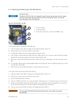
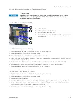
The KBox A-150-SKL is mounted on a DIN Rail in a control cabinet using a DIN rail clamp assembled on either the:
Top side of the chassis
Heat sink on the top side of the chassis
Rear side of the chassis
The position and direction of the DIN rail clamp decides the orientation of the KBox A-150-SKL within the control
cabinet. Therefore, when installing the DIN rail clamp take the following into consideration:
Do not obstruct the airflow over the heatsink, this can stop sufficient heat dispersing and causes a build-up of
heat.
Access to the front panel I/O connectors, power connector and external drive bay
To attach the DIN rail mounting clamp, perform the following
1.
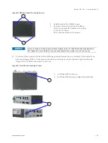
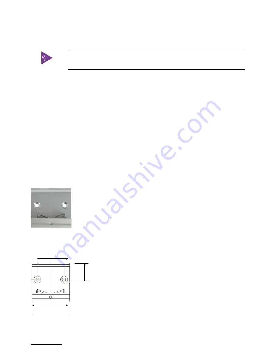
Make sure that the DIN rail mounting clamp is in the upper position, for the required mounting option.
Figure 18: DIN Rail Mounting Clamp Upper Position
2.
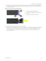
Fasten the DIN rail mounting clamp firmly using the supplied two x flathead (M4x6) screws only.
Figure 19: DIN Rail Clamp Screw Dimensions (Measurements in mm)
3.
Clip the top of the DIN rail mounting clamp in to the DIN rail and push the bottom of the DIN rail firmly until it
clamps on to the bottom of the DIN rail.
22
35.2
50

