KBox A-150-SKL - User Guide Rev. 1.1
// 21
4.1.1.
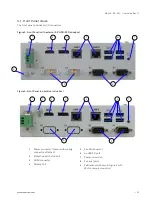
DC Input Power Connector
The 3-pin DC input power connector (PSC 1,5/ 3-M) connects to the appropriate DC main power supply using the
supplied DC mating connector (PSC 1,5/ 3-F), see Figure 3 and Figure 4, pos. 1. For information on how to wire the DC
mating power connector, see Chapter 8.3: Wiring the DC Mating Power Connector. For the pin assignment of the DC
input power connector, see Chapter 11.1.1: DC Input Power Connector (- +).
4.1.2.
Protective Earth Stud Bolt
There is a protective earth stud bolt on the front panel connected to the chassis GND. The position of the protective
earth stud bolt varies, see Figure 3, pos. 2 and Figure 4, pos. 2.
The position of the protective earth stud bolt varies depending on whether the product
variant includes an external 2.5” HDD/SSD drive bay.
4.1.3.
HDMI
There is one HDMI 1.4 interface (3840 x 2160 @ 30Hz), for video/audio solutions, see Figure 3 and Figure 4, pos.3. For
the pin assignment of the HDMI connector, see Chapter 11.1.2: HDMI Connector (HDMI).
4.1.4.
Display Port (DP)
There is one DP 1.2 interface (4096 x 2160 @ 60Hz) for video only, see Figure 3 and Figure 4, pos.4. For the pin
assignment of the DP connector, see Chapter 11.1.3: Display Port Connector (DP).
4.1.5.
Ethernet (LAN1, LAN2)
There are two GbE LAN ports both supporting 10/100/100 Mbit Ethernet, see Figure 3 and Figure 4, pos.5. For the pin
assignment of the RJ45 Ethernet connectors, see Chapter 11.1.4: GbE RJ45 Connectors (LAN1, LAN2).
4.1.6.
USB 3.0 Ports
There are four USB 3.0 ports (type A) allowing for the connection of a USB 3.0/USB 2.0 compatible devices, see
Figure 3 and Figure 4, pos.6. For the pin assignment of the USB 3.0 connector, see Chapter 11.1.5: USB 3.0 Connector.
4.1.7.
Power-On Switch
There is a power-on switch on the front panel to apply power or perform an orderly shutdown, see Figure 3 and
Figure 4, pos.7. The power-on switch is controlled by the power-on switch pin header, see Chapter 11.2.10: Power-on
Switch Pin Header.
4.1.8.
Serial Ports (X1, X2)
The two serial ports (X1) and (X2) support RS232/422/485, see Figure 3 and Figure 4, pos.8. The supported serial port
type is configured in the BIOS setup menu:
Advanced>Super IO Configuration> Serial Port # Configuration> Serial Port
# Type>.
For the pin assignment of the serial port connector, see Chapter 11.1.6: Serial Port Connectors (X1, X2)
4.1.9.
Breakouts (X3, X4)
The two breakouts can be used to install Wi-Fi antennas, if the WI-FI + Bluetooth combo mPCIe expansion card is
implemented, see Figure 3, pos.9 or for further custom IO expansion e.g. serial ports, see Figure 4, pos.9.


