KBox A-150-SKL - User Guide Rev. 1.1
// 29
4.
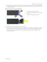
Insert a 9.5 mm high drive into the drive bay by carefully pushing the drive into the drive bay, with the drive’s
contacts facing inward, until the connectors attach. Alternatively, attach an extension frame to a 7 mm high drive
and insert the drive with extension frame into the drive bay with the drive’s contacts facing inward, until the
connectors attach.
Attaching an extension frame for 7 mm to 9.5 mm to 7 mm high drives adjusts the height and
ensure that the HDD/SSD is inserted correctly into the drive bays internal SATA data and
SATA power connectors.
5.
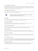
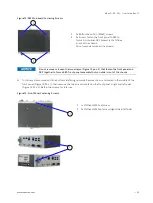
Push the drive bay cover into the closed position (Figure 11, pos. 1) until the drive bay eject button clicks.
Opening the System
6.2.
To access the internal component, open the system as described in this chapter and following the installing and
removing instructions and procedures.
Protection label
The KBox A-150-SKL is factory configured to meet customer requirements and then sealed
with a protection label. Opening the KBox A-150-SKL invalidates the warranty and may
cause damage to internal components.
Before opening the KBox A-150-SKL, the product must be switched off using the power-on
switch, and disconnect all peripheral devices. Disconnect the product from the AC mains
power supply by removing the power cable from the DC power supply or the mains power
socket. Observe the General Safety Instructions for IT Equipment within this user guide.
Only qualified personnel aware of the associated dangers must perform activities inside the
chassis!
KBox A-150 SKL is to be operated in closed condition only
It is only ensured that users do not have access to internal components during operation if
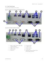
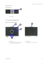
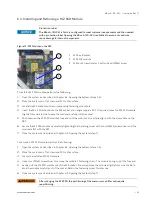
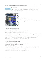
closed and the front panel SBC assembly screws (Figure 12, pos. 1) & (Figure 13, pos. 1 & 2)
are secured.
To access the internal component, perform the following:
1.
Close all applications. Shut down properly using the power-on switch and disconnect the power cable from the
DC main power source. Disconnect all peripherals.
2.
Place the KBox A-150-SKL on a flat, clean and ESD-safe surface.
3.
The front panel is attached to the mainboard. To open the chassis, release the front panel-mainboard assembly
by removing the two screws shown in Figure 12, pos. 1. Retain the screws for later use.


