KBox A-150-SKL - User Guide Rev. 1.1
// 37
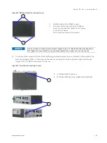
For the KBox A-150-SKL with Wi-Fi, the front panel keep out area depends on the implemented dual Wi-Fi antennas
and the orientation of the Wi-Fi antennas.
Figure 24: Keep Out Area for installed dual Wi-Fi Antenna (with external 2.5” HDD/SSD drive bay)
Wi-Fi antennas require an additional keep out area. Kontron’s reference Wi-Fi antennas
require a minimum of 40 mm horizontally and 135 mm in required antenna direction when
measured from the Wi-Fi connector.
Wiring the DC Mating Power Connector
8.3.
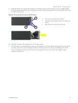
The DC input power connector connects to the DC power supply via the supplied DC mating power connector
(PSC 1,5/ 3-F) and the corresponding wiring connected to the DC mating power connector’s clamps (Figure 25, pos. 4,
5 & 6)
The wiring corresponding to the DC mating power connector is not included in the scope of
delivery.
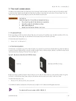
Figure 25: Phoenix Input Power Connector and Mating Power Connector
1
3-pin input power connector (PSC 1,5/ 3-M)
2
3-pin mating power connector (PSC 1,5/ 3-F)
3
Cover over the slotted pan head screws
4
Clamp for functional earth wire
5
Clamp for 0 VDC wire
6
Clamp for +24 VDC wire
2
6
5
4
1
3
40 mm
135 mm


