KSwitch D3 UM Unmanaged Fast Ethernet Switch - Preliminary User Guide, Rev. 0.9
// 21
4.1.3.
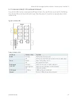
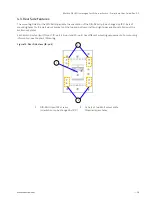
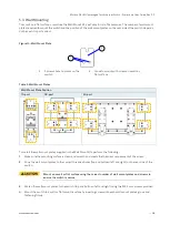
Indicator LEDs (P 1, P2, ALM and Ethernet)
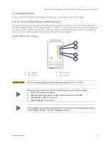
The indicator LEDs show the normal operation of the switch and in the case of failure may be used for faultfinding.
The indicator LEDs are contained within each copper/fiber Ethernet ports connector or as separate power/alarm
indicator LEDs.
Figure 5: Indicator LED
Table 4: Indicator LEDs
LED Name
Indicator/Color
Condition
P1/P2
On Green
P1/P2 power line has power
Off
P1/P2 power line disconnect or does not have supply power
Alarm
On Red
Power failure alarm occurs
Off
No power failure alarm
RJ45 Copper
(Link/Act)
On Green
Ethernet link up but no traffic is detected
Flashing Green
Ethernet link up and there is traffic detected
Off
Ethernet link down
RJ45 Copper
(Speed)
On Yellow
100Mbps connection detected
Off
No link, a 10Mbps connection is detected

