KSwitch D3 UM Unmanaged Fast Ethernet Switch - Preliminary User Guide, Rev. 0.9
// 27
5/
Mounting
Before installing the switch, consider the required orientation of the switch within the installation environment and
access to connectors.
Mount leaving a clearance of 20 mm around the switch, to ensure proper operation and to
prevent the switch from overheating.
Restricted Access
The switch’s intended use is in a Restricted Access Location, where only authorized service
personnel or users can gain access.
•
Service personnel or users have to pay special attention and take special precautions
before handling the switch.
•
Only authorized, well-trained professionals should be allowed to access the restricted
access location. Access should be controlled be the authority responsible for the
location with a lock and key or a security identity system
5.1.
DIN-Rail Mounting
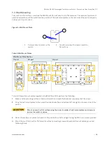
To mount the switch on a DIN-Rail, perform the following:
1.
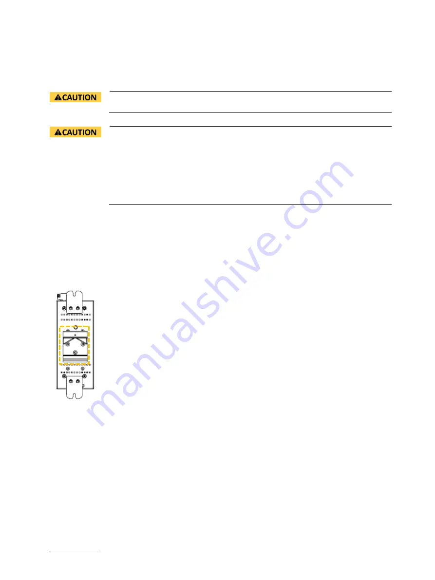
Fasten the DIN-Rail clip on the switch in the upper position (Figure 13) for the required mount orientation with the
screws (M3, 5 mm) provided.
Figure 13: DIN-Rail Clip
2.
Hook the top of the DIN-Rail clips over the DIN-Rail and push the bottom of the switch towards the DIN-Rail until
the Din-Rail clip snaps into place.
5.2.
DIN-Rail Removal
To remove the switch on a DIN-Rail, perform the following:
1.
Push the switch down to free the bottom of the DIN-Rail clip from the DIN-Rail.
2.
Rotate the bottom of the switch away from the DIN-Rail.
3.
Unhook the top of the DIN-Rail clip from the DIN-Rail by lifting upwards.

